background image

8

850 812  R. 10/15

 SAMOA Industrial, S.A. · Pol. Ind. Porceyo,  I-14 · Camino del Fontán, 831 · 33392 Gijón - Spain · Tel.: +34 985 381 488 · www.samoaindustrial.com

2015_10_27-13:40

WARNING

ATENCIÓN

d

o


not


over


tension


the


reel

excessive


strain


on


the


hose


and


reel


spring


could


damage


the


reel

.

To increase spring tension
1.

  Pull the hose out 10 feet (3 metres) and let the hose reel latch 

(fig. 11).

2. 

 Wind the hanging hose into the reel (fig. 13).

3. 

 Gently pull the hose, it will be automatically rewound (fig. 14).

4. 

 Repeat if more spring tension is required.

To decrease spring tension
1.

  Pull the hose out 10 feet (3 metres) and let the hose reel latch 

(fig. 11).

2.

  Unwind one turn and pull the hose (fig. 12).

3.

  Gently pull the hose, the hose is automatically rewound (fig. 14).

4. 

 Repeat if less spring tension is required.

EN

n

o


añada


demasiadas


vueltas


al


enrollador

. u

na


tensión


excesiva


podría


dañar


el


muelle


y


la


manguera

.

Para dar tensión
1. 

 Extraiga unos 10 pies (3 metros) de manguera y trinque la 

manguera (fig. 11).

2. 

 Introduzca una vuelta de la manguera, en el disco del enrollador 

(fig. 13).

3.

  Tire suavemente de la manguera hasta que quede liberada del 

trinquete y se recoja por si misma (fig. 14).

4.

  Repita los pasos anteriores si necesita más tensión.

Para quitar tensión
1. 

 Extraiga unos 10 pies (3 metros) de manguera y trinque la 

manguera (fig. 11).

2. 

 Quite una vuelta de manguera del interior del disco del 

enrollador (fig. 12).

3.

  Tire suavemente de la manguera hasta que quede liberada del 

trinquete y se recoja por si misma (fig. 14).

4.

  Repita los pasos anteriores si necesita menos tensión.

ES

Fig. 8b

Fig. 9

ATENÇÃO

a

ntes


de


retirar


a


mangueira

fechar


o


registro


da


linha


que


estiver


mais


próxima


do


carretel


e


acionar


o


comando


de


graxa

para


eliminar


toda


a


pressão


da


graxa


da


mangueira

.

NOTA: 

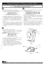
Durante a instalação da mangueira, apertar o fixador 

somente até ter uma pequena deformação na mangueira. Evitar 
apertar demais o fixador, pois a mangueira pode romper.

1.

  Desenrolar totalmente a mangueira usada e procurar a posição 

de bloqueio do trinquete mais próxima a longitude mostrada na 
figura 6.

2.

  Afrouxar os parafusos da abraçadeira de parada e desmonta-la 

(figura 7)

3.

  Desconectar a mangueira como indicado na figura 8a e liberar a 

mangueira da roda retirando os fixadores da mangueira do 
suporte interno do carretel (figura 8b).

4.

  Conectar a nova mangueira, introduzindo sua extremidade na 

saída do carretel e no orifício da roda até chegar ao giratório, então 
conectar novamente a mangueira no carretel e fixar o fixador. 
Colocar a abraçadeira de parada na extremidade livre da mangueira.

5.

  Liberar o trinquete e soltar lentamente a mangueira para enrola-

la (figura 9).

PT

Maintenance and repair procedures / Procedimientos de mantenimiento y reparación / 

Procédures de maintenance et de réparation / Service und Wartung / Procedimentos de Manutenção e Reparos

Hose installation / Instalación de la manguera / Montage du flexible / 

Schlauchmontage / Instalação da Mangueira

Spring load adjustment / Ajuste de la tensión del resorte / 

Réglage de la tension du ressort / Ändern der Federstärke / Ajuste da Tensão da Mola

Содержание 506 Series

Страница 1: ...etergentes lubricantes grasa y otros fluidos seg n modelos Al tirar de la manguera esta se desenrolla pudiendo bloquearse a la longitud deseada por acci n de un trinquete Para recoger la manguera bast...

Страница 2: ...es et des solvants qui sont compatibles avec les mat riaux des parties humides de l enrouleur liminer pr alablement la pression interne du fluide au cours des op rations d entretien Le ressort est tou...

Страница 3: ...A Zudem kann er auch auf einer schwenkbaren Konsole Fig B montiert werden Um die ideale Position des schlauchf hrenden Arms zu erreichen kann er wie folgt montiert werden SENKRECHTER SCHLAUCHAUSZUG E...

Страница 4: ...la manguera por la salida de manguera y coloque el tope manguera de nuevo 6 Quite el sargento para liberar el disco del enrollador ES Pour repositionner le bras de guidage du flexible la proc dure est...

Страница 5: ...gure 8a and fix the U bolt as shown in figure 8b 5 Fix the hose stop to the free end of the outlet hose 6 Pull out the hose slightly to free the spool latch and then gradually release the hose to allo...

Страница 6: ...bank 2 Rollen Sie den Aufroller um 16 Umdrehungen bei 10 Meter 33 L nge 19 Umdrehungen bei 15 Meter 49 L nge 21 Umdrehungen bei 15 Meter 49 L nge ab um den Aufroller vorzuspannen 3 F hren Sie nun das...

Страница 7: ...enrouleur et ouvrez la poign e de distribution pour lib rer la pression du fluide l int rieur du tuyau NOTE Lors de l installation du tuyau serrez le boulon en U graduellement jusqu ce que le tuyau s...

Страница 8: ...a que quede liberada del trinquete y se recoja por si misma fig 14 4 Repita los pasos anteriores si necesita menos tensi n ES Fig 8b Fig 9 ATEN O Antes de retirar a mangueira fechar o registro da linh...

Страница 9: ...ros WARNUNG Bringen Sie nicht zuviel Spannung auf die Spule berm ssiger Beanspruchung vom Schlauch und Feder schadet den Aufroller Federst rke Erh hen 1 Ziehen Sie den Schlauch 3 Meter heraus und lass...

Страница 10: ...close the nearest shut off valve to the reel and open the fluid control gun to release the pressure inside the hose 1 Pull the hose out and let the hose reel latch fig 15 2 Unscrew the nuts with two...

Страница 11: ...o e Reparos Bevor Sie das abgenutzte Eingangsgelenk abmontieren schliessen Sie das Ventil das am n chsten zum Schlauchaufroller montiert ist und ffnen Sie die sich am Ende befindende Pistole um den D...

Страница 12: ...o inverso FR 1 Retirer le boulon qui fixe le cliquet sur le bras de l enrouleur fig 18 2 Remplacer le cliquet et ou le ressort d fectueux 3 Effectuer les tapes ci dessus en sens inverse DE 1 Entfernen...

Страница 13: ...e ou le ressort est cass Augmenter la tension du ressort ou le remplacer Fuite au niveau du flexible Le flexible est perc ou endommag Remplacer le flexible Fuite au niveau de la rotule La rotule est d...

Страница 14: ...13 40 526011 526010 526012 526013 750429 750424 850444 850310 850311 850313 850617 850613 850615 850614 950510 850442 944810 944816 941126 850446 852600 852601 852602 850502 942106 941105 941006 94092...

Страница 15: ...te U bolt AISI 316 526002 Hose stop and U bolt kit 944816 U bolt AISI 316 941126 x2 Nut AISI 316 852602 x2 Hose stop 940372 x2 Screw 941105 x2 Nut 850 446 Plate u bolt Aisi 316 Kit No Part No incl Des...

Страница 16: ...1 2 944816 Abarc n AISI 316 941126 x2 Tuerca autoblocante AISI 316 852602 x2 Bicono 940372 x2 Tornillo 941105 x2 Tuerca autoblocante 850 446 Pletina abarc n AISI 316 ES C d kit C d incl Descripci n 52...

Страница 17: ...autobloquant AISI 316 852602 x2 But e 940372 x2 Vis 941105 x2 crou autobloquant 850 446 Platine pour boulon en U AISI 316 FR Kit Nr R f rences incluses D signation 526004 Kit but e d arr t pour flexib...

Страница 18: ...14 Federdeckel 940522 x6 Schraube 850442 Federscheibe Art Nr Beschreibung 850310 Feder standard 10 m 33 850311 Feder verst rkt 15 m 49 850313 Feder extra verst rkt 15 m 49 Kit Nr Artikelnummer Beschre...

Страница 19: ...x2 Parafusos 941105 x2 Porca de seguran a 850 446 Pletina abarc n AISI 316 PT C d kit C d incl Descri o 526004 Abra adeira de parada da mangueira gua quente 3 8 y graxa 1 4 944810 Abra adeira AISI 31...

Страница 20: ...Gij n Spain declares that this product conforms with the EU Directive 2006 42 EC EN SAMOA INDUSTRIAL S A Pol Ind Porceyo I 14 Camino del Font n 831 33392 Gij n Espa a declara que este producto cumple...

Отзывы: