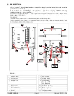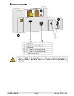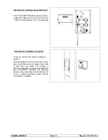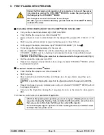
Assemble filters at the outlet of the BASE and CATA pumps.
Assemble pressure regulators at the outlet of the BASE and CATA pumps.
Install the fluid and air hoses between the pumps and the CYCLOMIX
TM
MICRO, and between the
CYCLOMIX
TM
MICRO and the gun. When choosing the fluid hoses, comply with the pressures delivered
by the pumps. For the air hoses, install
non-static
hoses.
Unscrew the regulators before supplying air to the installation.
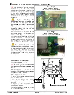
Check that the three way-valve is in the
IN fluid circuit sense and not in the TA circuit sense.
Nota : To connect the SOLVENT pump (CATA) to the CYCLOMIX MICRO :
-
choose a CYCLOMIX
TM
MICRO set up with 1 catalyst and one cata solvent,
-
or disconnect the CATA hose at non-return valve level (CATA) of the equipment and replace it
connecting the SOLVENT hose (CATA).
6. OPERATING
DRIVING FROM THE CYCLOMIX
TM
MICRO
SCREEN
The different menus and the informations relating to the CYCLOMIX
TM
MICRO are displayed on the
alphanumeric screen.
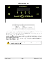
KEYBOARD
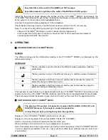
ESC
That key enables to quit the menus or the different modes (production, flushing,
parameters).
↵
That key enables to enter in the different menus or to validate a value of parameter.
▲
That key enables to shift from a menu to another and to increase the value of a
parameter during modifications of value.
▼
That key enables to shift from a menu to another and to decrease the value of a
parameter during modifications of value.
The keyboard is used thanks to a magnet provided with the CYCLOMIX
TM
MICRO. That piloting mode
enables to drive the CYCLOMIX
TM
MICRO inside the booth if the box is installed behind the booth glass.
That technology enables the operator to save time and to carry out his work from the application place.
SWITCHING ON THE CYCLOMIX
TM
MICRO
The placing of the system into operation requires that the BASE, CATALYST and
SOLVENT drums are full enough to ensure the production.
Connect the gun before placing the system into operation.
Supply air to the CYCLOMIX
TM
MICRO (minimum 4 bar / 58 psi).
Supply air to the air regulators of the pumps (BASE, CATALYST, SOLVENT).
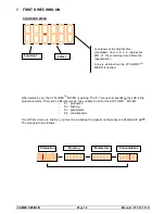
Switch on the control unit (switch located on the side of the unit).
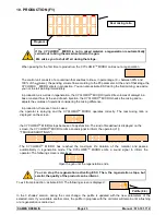
When switching on the control unit, a menu is displayed on the screen.
Nota : Parameters have been programmed in the factory before the delivery of the CYCLOMIX
TM
MICRO.
You must adapt the parameters to the use. They must be modified by an authorized person (refer to list
of parameters).
SAMES KREMLIN
Page 15
Manual : 573.191.112

