3. OPERATING PRINCIPLE
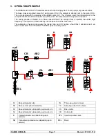
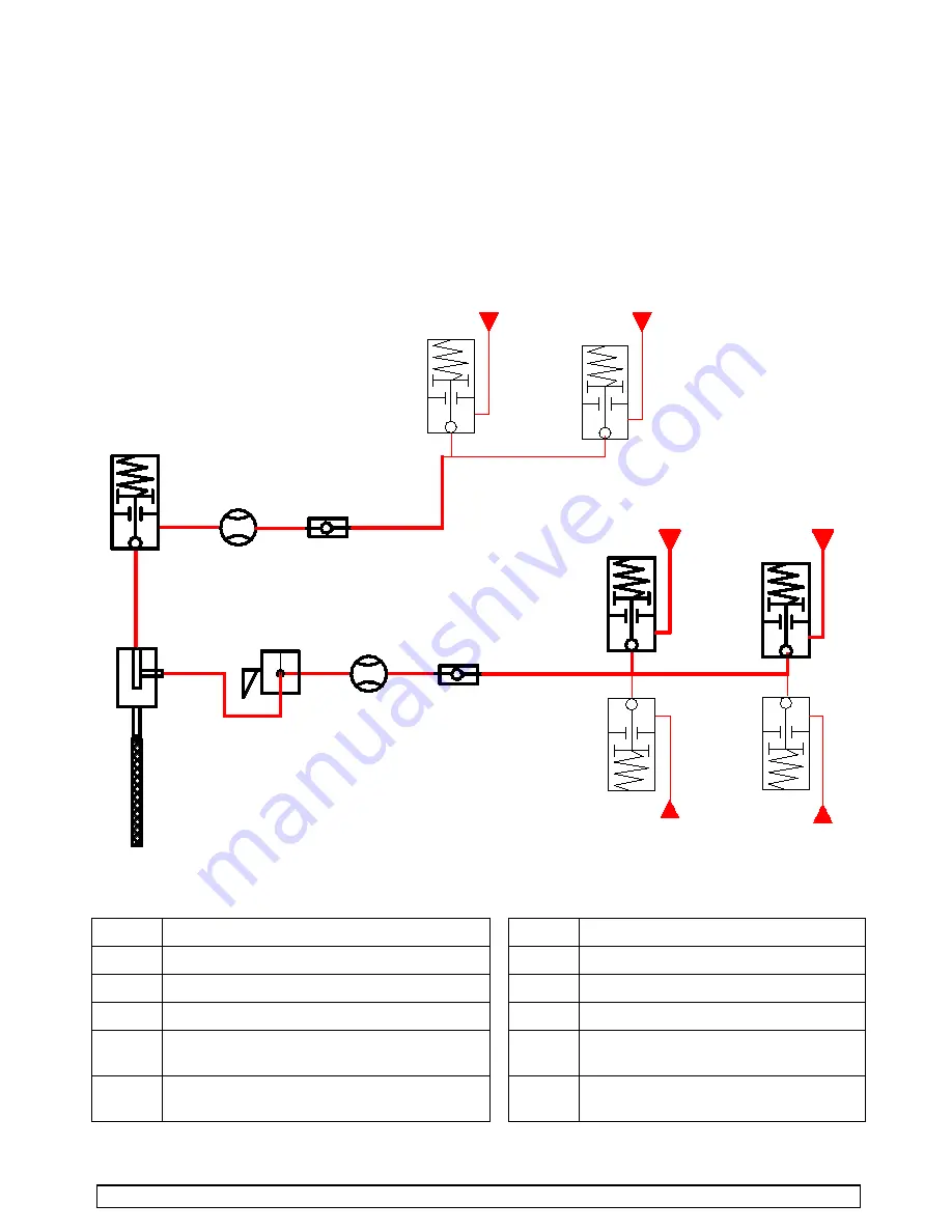
The 2 BASE and CATALYST materials are sent to the mixing system from 2 pumps or pressure tanks.
The base crosses a piloted valve (A1) and a meter (CA), the catalyst is directly sent to the meter (CB).
The cycle begins with the opening of the BASE valve (A1). The 2 meters send their informations to the
computer that shuts off the catalyst valve (VP6) when the computerized mixing ratio is reached.
The mixing process is based on a base constant flow. The catalyst flow is injected low under high
frequency. The injection is made directly into the base flux at the mixer level.
The automaton checks continuously the mixing ratio and if it notices a fault that it cannot correct, an
alarm is activated. The CYCLOMIX
TM
MICRO goes on safety mode.
TA
vp6
A1
SA
CB
CA
AR2
AR1
IN
A
SA
MEL
A2
A3
A
A
B1
SB
B
SB
A1
Base piloted valve (A)
IN
Three way-valve to mixer
SA
Base solvent piloted valve(SA)
TA
Sampling outlet for the base
A2
Base piloted valve (depending upon version)
CA
Base meter
A3
Base piloted valve (depending upon version)
CB
Cata meter
B
Catalyst piloted valve (depending upon
version)
VP6
Injection piloted valve
SB
Cata solvent piloted valve (depending upon
version)
MEL
Mixer
SAMES KREMLIN
Page 7
Manual : 573.191.112

