background image

7

RIS 400_700PE/PW EKO 3.0

www.salda.lt

[ lt ]

[ it ]

[ en ]

[ de ]

- Maintenance and repair should only be per-

formed by experienced and trained staff.

- The  fan  should  be  inspected  and  cleaned  if 

needed at least 1/year.

- Be sure the fan is disconnected from power 

source  before  performing  any  maintenance 

or repair.

- Proceed to maintenance and repair after any 

rotation in the fan stopped.

- Observe staff safety regulations during main-

tenance and repair.

- The motor is of heavy duty ball bearing con-

struction. The motor is completely sealed and 

requires no lubrication for the life of the motor.

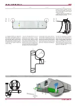
- Detach fan from the unit.

- Impeller should be specially checked for buil-up 

material or dirt which may cause an imbalance.  

Excessive  imbalance  can  lead  to  accelerated 

wear on motor bearings and vibration.

-  Clean  impeller  and  inside  housing  with  mild 

detergent, water and damp, soft cloth.

- Do not use high pressure cleaner, abrasives, 

sharp instruments or caustic solvents that may 

scratch or damage housing and impeller.

- Do not plunge impeller into any fluid.

-  Make  sure,  that  impeller’s  balance  weights 

are not moved.

- Make sure the impeller is not hindered.

- Mount the fan back into the unit. Connect the 

fan to power supply source.

- If the fan does not start after maintenance or 

repair, contact the manufacturer.

- Montage und Elektroarbeiten nur durch aus-

gebildetes  und  eingewiesenes  Fachpersonal 

und nach den jeweils zutreffenden Vorschriften 

ausführen. 

- Die Anlage muss min. einmal pro Jahr geprüft 

und gereinigt werden.

- Vor der Wartung oder Reparatur sicherstellen, 

dass die Anlage vom Stromnetz getrennt ist.

- Arbeiten dürfen nur bei abgeschaltetem und 

mechanischem Stillstand des Laufrades sowie 

nach Abkühlung  der  Heizung  vorgenommen 

werden! Gegen Wiedereinschalten sichern! 

- Arbeitssicherheitsregelungen bei der tech-

nischen Bedienung beachten. 

- In der Motorkonstruktion sind hochwertige 

Lager eingebaut. Die Lager sind eingepresst 

und erfordern keine Schmierung. 

- Ventilator von der Anlage abschalten.

- Die Flügel vom Ventilator auf Ablagerungen 

und Staub prüfen, starke Verschmutzung kann 

zu  Unwucht  führen.  Die  Unwucht  verursacht 

eine Vibration und schnelleren Lagerverschleiß.

- Flügel und Gehäuse mit einem sanften Rei-

nigungsmittel  abwaschen,  keine  aggressiven 

Putzmittel verwenden die das Material angreifen 

könnten. Flügel und Gehäuse danach mit viel 

Wasser  gründlich  reinigen,  keine  Hochdruck-

anlage,  Putzmittel,  scharfes  Werkzeug  oder 

aggressive  Stoffe  verwenden,  die  zu  Kratzer 

und Beschädigungen führen könnten.

- Beim Reinigen der Flügel Motor vor Feuch-

tigkeit und Nässe schützen.

-  Prüfen,  dass  die  Wuchtgewichte  am  Flügel 

nicht verschoben werden.

- Flügel darf nicht am Gehäuse streifen.

-  Montieren des Ventilators wieder in die An-

lage. Anschließen die Anlage ans Stromnetz.

-  Sollte  sich  nach  Wartung  der Anlage  der 

Ventilator  nicht  mehr  einschalten  lassen  oder 

der  Thermokontaktschutz  auslösen,  an  den 

Hersteller wenden.

-  Während  der  Wartung  den  Ventilator,  der 

herausgenommen/  eingelegt  wird,  nicht  an 

Laufradflügel halten, weil es zu Unwucht/ Be-

schädigung des Laufrades führen kann. Nur am 

Ventilatorgehäuse halten.

-  Solo  personale  esperto  e  qualificato  può 

effettuare lavori di manutenzione straordinaria.

- Il ventilatore deve essere ispezionato visiva-

mente e pulito almeno una volta all’anno.

- Prima di effettuare i lavori di manutenzione e 

di riparazione assicurarsi che il dispositivo sia 

scollegato dalla rete elettrica.

- Effettuare i lavori di manutenzione solo quan-

do tutte le parti del ventilatore si sono fermate.

-  Durante  i  lavori  di  manutenzione  tecnica, 

attenersi alle opportune disposizioni di sicurezza 

sul lavoro.

- Nel corpo del motore sono inseriti i cuscinetti 

ad altre efficienza. Sono sigillati e non richiedono 

alcuna  lubrificazione  per  tutta  la  durata  della 

vita del motore.

- Scollegare il ventilatore dall’unità. 

- È necessario ispezionare accuratamente la 

girante  del  ventilatore,  controllando  che  non 

si sia accumulata polvere o altre sostanze che 

potrebbero sbilanciare la ventola. Lo sbilancia-

mento provoca vibrazioni e accelera l’usura dei 

cuscinetti del motore.

- Pulire la ventola e la parte interna del corpo 

con acqua e detergente delicato non corrosivo.

- Per pulire la ventola non utilizzare apparecchi 

ad  altapressione,  prodotti  abrasivi,  strumenti 

appuntiti  e  solventi  aggressivi  che  possono 

graffiare o danneggiare la ventola.

- Durante la pulizia della ventola non immergere 

motore nell’acqua.

- Assicurarsi che i pesi di bilanciamento della 

ventola siano nella loro sede.

- Assicurarsi che la ventola non sfreghi contro 

il corpo dell’unità.

- Reinserire il ventilatore nel dispositivo. Colle-

gare alla rete elettrica.

- Se dopo la manutenzione il ventilatore non si 

accende oppure la protezione termica entra in 

azione, contattare il produttore.

- Aptarnavimo darbus turėtų atlikti tik patyrę ir 

apmokyti darbuotojai.

-  Ventiliatorius  turi  būti  apžiūrimas  ir  valomas 

mažiausiai 1 kartą per metus.

-  Prieš  pradedant  aptarnavimo  ar  remonto 

darbus  įsitikinkite,  ar  įrenginys  atjungtas  nuo 

elektros tinklo.

- Aptarnavimo darbus pradėkite tik sustojus bet 

kokiam judėjimui ventiliatoriuje.

- Vykdydami techninio aptarnavimo darbus lai-

kykitės visų darbo saugos taisyklių.

-  Variklio  konstrukcijoje  panaudoti  aukšto  na-

šumo guoliai. Jie yra užpresuoti ir nereikalauja 

jokio tepimo per visą variklio tarnavimo laiką.

- Atjunkite ventiliatorių nuo įrenginio.

-  Būtina  kruopščiai  apžiūrėti  ventiliatoriaus 

sparnuotę,  ar  nesusidarė  dulkių  ir  kitokių  me-

džiagų  apnašos,  galinčios  išbalansuoti  spar-

nuotę. Išbalansavimas sukelia vibraciją ir grei-

tesnį variklio guolių susidėvėjimą.

- Nuvalykite sparnuotę ir korpuso vidų švelniu, 

netirpdančiu bei korozijos neskatinančiu plovi-

kliu ir vandeniu.

-  Valydami  sparnuotę  nenaudokite  aukšto 

slėgio  įrenginių,  šveitiklių,  aštrių  įrankių  arba 

agresyvių  tirpiklių,  galinčių  įbrėžti  ar  pažeisti 

sparnuotę.

-  Valydami  sparnuotę  nepanardinkite  variklį  į 

skystį.

- Įsitikinkite, ar sparnuotės balansiniai svarsčiai

savo vietose.

- Įsitikinkite, ar sparnuotė nekliūna už korpuso.

- Sumontuokite ventiliatorių atgal į įrenginį. Pri-

junkite prie elektros tinklo.

- Jei po aptarnavimo darbų ventiliatorius neįsi-

jungia, arba savaime įsijungia termokontaktinė 

apsauga - kreipkitės į gamintoją.

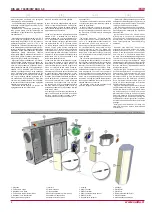
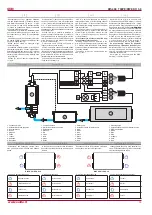
7. Šilumokaitis

8. Šalinamo oro temperatūros jutiklis

9. Tiekiamo oro ventiliatorius

10. Elektrinis šildytuvas (tik RIS PE EKO 3.0)

11. Apėjimo sklendė

12. Automatikos dėžė

13. Ištraukiamo oro dregmės ir temeperatūros 

jutiklis.

7. Scambiatore di calore

8. Sensore temperatura di estrazione

9. Ventilatore di mandata

10. Batteria elettrica (solo RIS PE EKO 3.0)

11. Valvola by-pass

12. Scatola di comando

13.  Sensore  umidità  e  temperatura  della 

estrazione

7. Heat Exchanger

8. Exhaust air temperature sensor

9. Supply air fan

10. Electrical heater (

just

 RIS PE EKO 3.0)

11. By-pass valve

12. Control Box

13. Temp. and humidity sensor for extract air.

7. Wärmetauscher

8. Temperaturfühler der Fortluft

9. Zuluft-Ventilator

10. Elektrischer Wärmer (

nur

 RIS PE EKO 3.0)

11. Bypass-Klappe

12. Steuerkasten

13. Abluftfeuchte- und Temperaturfühler.

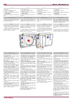
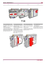
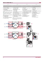
Unplug  unit  from  mains  first  and  wait  for  2 

minutes  (till  fans  fully  stop)  before  opening 

the covers.

Bevor  die  Gerätetüren  geöffnet  werden 

dürfen, Gerät elektrisch vom Versorgungs

-

netz trennen und etwa 2 Min. warten, bis die 

Ventilatoren völlig stehen bleiben.

Prieš atidarydami agregato duris būtinai atjun-

kite elektros srovę ir palaukite, kol pilnai nustos 

suktis ventiliatoriai (apie 2 min.).

Prima di aprire lo sportello dell'unità è neces-

sario togliere l'alimentazione ed attendere che i 

ventilatori siano del tutto fermi (circa 2 minuti).

Dirt increases air resistance in the filter, there-

fore less air is supplied into the premises.

- It is advisable to change the filters every 3-4 

months, or in accordance with the readings of 

filter contamination sensor. (Sensor PS 600 is 

integrated in the unit).

Verunreinigte Filter erhöhen die Druckverluste, 

d.h. ein geringeres Luftvolumen gelangt in die 

Räume.

- Die Filter werden ca. alle 3 Monate bzw. je 

nach Signal der Filterüberwachung ersetzt. (Die 

Druckdosen PS600B sind im Gerät eingebaut).

Užsiteršę filtrai, didina oro pasipriešinimą, dėl 

to sumažėja į patalpas paduodamo oro kiekis.

- Filtrus patartina keisti kas 3-4 mėnesius arba 

pagal filtro užterštumo jutiklio parodymus (juti-

klis PS 600 integruotas į agregatą).

I  filtri  sporchi  aumentano  la  resistenza  al 

passaggio  dell'aria  riducendone  la  portata  ed 

aumentando i consumi elettrici.

SI consiglia di sostituire i filtri ogni 3/4 mesi o 

in  funzione  dell'indicazione  di  un  pressostato 

differenziale (fornito come optional).

Содержание RIS 400PE/PW EKO 3.0

Страница 1: ...vviso Subject to technical modification RIS 400_700PE PW EKO 3 0_P0023_AP_0004 REKUPERATORINIAI RENGINIAI CENTRALE DI VENTILAZIONE CON RECUPERO DI CALORE AHU WITH HEAT RECOVERY L FTUNGSGER TE MIT W RM...

Страница 2: ...eristiche del processore e dei gruppi del sistema 28 Controllo periodico dell unit 31 Garanzia 31 Schema elettrico 34 Tabella di manutenzione del prodotto 62 lt Turinys Transportavimas ir saugojimas 4...

Страница 3: ...tion diagrams 34 Product maintenance table 62 de Inhalt Transport und Lagerung 4 Beschreibung 4 Schutzmassnahmen 4 Betriebsbedingungen 5 Bestandeile des Ger tes 6 Bedienung 6 Filter 6 Ventilator 7 W r...

Страница 4: ...letzungsgefahr oder Gefahr mechanischer St rungen Bei der Montage und Inbetriebnahme muss Sicherheitskleidung getragen werden Vorsicht die Winkel und Kanten der Anlage und der Kom ponenten k nnen scha...

Страница 5: ...supply extract only clean air free of chemical compounds causing metal cor rosion of substances aggressive to zinc plastic and rubber and of particles of solid adhesive and fibred materials The worki...

Страница 6: ...ciclo di prova Se durante tale ciclo la temperatura dell aria immessa dovesse scendere sotto il limite im postato dalla fabbrica l unit verrebbe fermata dopo circa 3 minuti Un messaggio che avverte de...

Страница 7: ...n acqua e detergente delicato non corrosivo Per pulire la ventola non utilizzare apparecchi ad altapressione prodotti abrasivi strumenti appuntiti e solventi aggressivi che possono graffiare o dannegg...

Страница 8: ...a rete elettrica Effettuare i lavori di manutenzione solo quan do tutte le parti dei ventilatori si sono fermate La pulizia dello scambiatore di calore viene effettuata una volta all anno Estrarre del...

Страница 9: ...professional If necessary the electrical heater can be re moved Disconnect the electrical connector from the heater and remove the heater Das Elektro Heizregister bedarf keiner zus tz lichen Wartung E...

Страница 10: ...do control input Steuerungsignal VDC 0 10 apsaugos klas classe di protezione protection class Schutzart IP54 Bendra naudojama galia Potenza assorbita totale Total power consumption Total Leistungsaufn...

Страница 11: ...otal Leistungsaufnahme galia srov potenza corrente power current Nennleistung Nennstrom kW A 1 54 8 34 3 34 15 84 4 84 9 34 0 34 2 84 Valdymo automatika sumontuota Regolazione integrata Automatic cont...

Страница 12: ...Gylis Profondit Depth Tiefe L2 mm 46 46 Tiekimo Immissione supply Zuluft F7 F7 Plotis Larghezza Width Breite L mm 300 445 Auk tis Altezza Height H he H mm 220 210 Gylis Profondit Depth Tiefe L2 mm 46...

Страница 13: ...the heater works using the same directions the mean temperature difference decreases which affects the heater efficiency If there is a possibility for condensate or water to access the unit external p...

Страница 14: ...se utilizzati come opzione devono essere montati il pi lontano possibile dall unit ventilante per quanto permette la lunghezza del cavo del sensore fino alla prima derivazione o curva della rete aerau...

Страница 15: ...Es ist notwendig Siphon f r tropfende Kondensat zu verwenden Zubeh r Das Ablaufsystem darf nur in R umen betrieben werden in welchen die Raumtemperatur nicht unter 0 C sinkt Ansonsten muss das System...

Страница 16: ...AVS Apvalus kanalinis vandeninis ildytuvas M1 oro ap jimo sklend s By pass pavara PR plok telinis ilumokaitis IV Ventilatore di estrazione PV Ventilatore di immissione RR Scambiatore rotativo R Motor...

Страница 17: ...VVP VXP RIS PW EKO 3 0 2 3 eigis vo tuvas Valvola a 2 3 vie 2 3 way valve 2 3 Wege Ventil CO2 CO2 keitiklis Sensore di CO2 CO2 transmitter CO2 sender S 1141 Skirtuminio sl gio keitiklis Sensore di pr...

Страница 18: ...3 pozicij valdymo signalas M6 ildytuvo vo tuvo pavara La temperatura dell aria immessa pu essere regolata in base a quella rilevata sull aria estratta impostando il setpoint mediante il pannello di c...

Страница 19: ...4 2 e 6 4 3 del manuale FLEX L utente pu regolare la velocit dei ventilatori a tre livelli ciascun livello pu essere modificato the set temperature is not reached the heater electric or water is swit...

Страница 20: ...acht der Regler RG1 aus Geschwindigkeit der Ventilatoren f r ZU und Abluft kann synchron oder asynchron geregelt werden siehe Beschreibung des Pults FLEX Punkt II 6 7 und II 6 8 Falls ein Wasserheizer...

Страница 21: ...i ripristina autono mamente al rientro nelle temperature di esercizio corrette quella manuale deve essere ripristinata premendo il pulsante rosso RESET sul coper chio della batteria Quando si attiva l...

Страница 22: ...ori RS485_1 pannello comando remoto FLEX e RS485_2 rete ModBus oppure pannello comando remoto STOUCH Valore dei contatti del connettore RJ11 1 COM 2 A 3 B 4 24V I microinterruttori 1 e 2 di fig 3 sono...

Страница 23: ...ri attivi 01h_Read_Coils 13 1 lt Ventiliatoriai jungti it Ventilatori attivi en Fans ON de L fter EIN 1 Attiva o Inattiva 13 InDumpper 04h_Read_Input 14 1 lt I or s oro sklend s pavara it Servomotore...

Страница 24: ...t Speisekabel muss laut elektrischen Param etern der Anlage gew hlt werden falls die Speiseleitung der Anlage fern vom Aggregat ist ist es n tig den Abstand und Spannungs fall zu bewerten Die Anlage m...

Страница 25: ...justment works must be done only by qualified and trained personnel Automatic control system of the ventilation unit must be properly adjusted to work adequately Also install measuring and operating d...

Страница 26: ...26 RIS 400_700PE PW EKO 3 0 www salda lt lt it en de Set 5 o C...

Страница 27: ...des RG1 Reglers 315 mA pr fen Gedimas agregato elektros sujungimuose jungtyse Malfunzionamento del collegamento elettrico morsettiera dell unit Possible unit fault at electrical connections of the un...

Страница 28: ...atore i fermo i Fan s not working Ventilator en nicht funktioniert Tiekiamo PV arba i traukiamo IV oro ventiliatoriaus gedimas Malfunzionamento del ventilatore di immissio ne PV o estrazione IV Supply...

Страница 29: ...sonda di temperatura con una nuova Verificare il termostato antigelo In condizioni normali la temperatura misurata dalla sonda deve essere maggiore di quella impostata sul termostato il contatto tra...

Страница 30: ...30 RIS 400_700PE PW EKO 3 0 www salda lt lt it en de...

Страница 31: ...cita I O type Typ I O Maks apkrova Carico massimo Max load Max Be lastung Min apkrova Carico minimo Min load Min Belastung A mA X10 L 230V 50Hz tiekiama tampa L Tensione 230V 50Hz L 230V 50Hz power su...

Страница 32: ...50hz Apertura della valvola PWM 24V 50hz Cooling valve opening PWM 24V 50hz ffnen der K hlungsklappe PWM 24V 50hz AO X33 4 VAL Au intuvo sklend s u darymas PWM 24v 50hz Chiusura della valvola PWM 24v...

Страница 33: ...M X34 5 A3 Filtr u ter tumo apsauga Protezione intasamento filtri Filter guard Filter Schmutzschutz DI X34 6 A3 COM X34 7 A4 Ventiliatori apsauga Protezione ventilatori Fans guard Fans guard DI X34 8...

Страница 34: ...eliver the equip ment to manufacturer Delivery costs should be covered by customer Alle von uns produzierte Ger te sind bei uns ab Werk gepr ft und getestet Sie sind von guten Arbeitsordnung Auf dem G...

Страница 35: ...33 18 X33 14 X33 13 X35 1 X35 2 Y1 Control OPEN AC 24 V Y2 Control CLOSE AC 24 V G System potential AC 24 V 24VDC X16 1 2 1 3 X33 5 X33 4 X33 3 VAL VAL VAL Y1 Y2 24VAC 3 position M5 G 11 14 COM B 0 10...

Страница 36: ...COM X12 X42 X37 2 X37 1 COM V2 X37 3 X37 4 X4 X3 ModBus RTU RS485_2 RS485_2 A1 A1 A2 A2 A3 A3 TE TE X52 X33 19 X33 20 COM T WAT TJ X33 22 X33 21 X35 3 X35 4 X35 5 N L supply L control N N N EXT EXT EX...

Страница 37: ...2 2 1 2 3 X29 1 3x1000W 230V KE1 A2 A1 PWM 0 TK TK RG2 Lin Lout 9 8 7 6 24VDC 24VDC X41 1 X41 2 X39 2 X39 1 X38 1 X38 2 X40 3 X40 2 X40 1 X34 8 X34 7 X34 6 X34 5 X34 4 X34 3 X34 2 X34 1 X33 26 X33 25...

Страница 38: ...3 1 Q1 26 24V DC 27 intput 0 10V DC 28 GND Transmitter 2 24 VDC P 28 27 26 X33 22 X33 21 COM T set 16 15 X16 2 HR A4 A4 PUMP AC N L N V1 COM X12 X42 X37 2 X37 1 COM V2 X37 3 X37 4 X4 X3 ModBus RTU RS4...

Страница 39: ...COM A 0 10 L X31 24VDC 24VDC X41 1 X41 2 X39 2 X39 1 X38 1 X38 2 X40 3 X40 2 X40 1 X34 8 X34 7 X34 6 X34 5 X34 4 X34 3 X34 2 X34 1 X33 26 X33 25 X33 17 X33 12 X33 18 X33 14 X33 13 X35 1 X35 2 Y1 Cont...

Страница 40: ...ze 5x20 Air quality transmitter Supply air pressure Air quality transmitter CO2 Extract air pressure FA Jumper A2 A1 A2 A1 7 2 1 X21 YE GN BU RD PWM STOP NO START NC X33 15 X33 16 COM A 0 10 L X31 24V...

Страница 41: ...Jumper FA 7 2 1 X21 YE GN BU RD PWM STOP NO START NC X33 15 X33 16 COM A 0 10 L X31 24VDC 24VDC X41 1 X41 2 X39 2 X39 1 X38 1 X38 2 X40 3 X40 2 X40 1 X34 8 X34 7 X34 6 X34 5 X34 4 X34 3 X34 2 X34 1 X...

Страница 42: ...6 7 24VDC 11 14 X16 3 7 8 R1 A1 A2 M4 1f 230V AC PE L N 3 1 P DX Cooling Jumper BOOST STOP NO START NC Transmitter 1 24 VDC 23 24V DC 24 intput 0 10V DC 25 GND Fan fall 1 2W max 1 2W max Fan run P 24V...

Страница 43: ...TL 1 2 TE 1 2 U RH TA GN YE RD WH GND RH 5V TA DTJ100 X10 X8 X42 X12 A4 1 A4 2 COM V1 T OUT COM X41 1 X41 2 COM V2 X40 1 X40 2 X40 3 X38 1 X38 2 RG1 V2 5 01 3 2 Components and cables indicated in dott...

Страница 44: ...L control M2 3 position 24VAC DC Y1 open Y2 close G M5 M5 Jumper 24VDC 0 10VDC GND Transmitter 2 24VDC 0 10VDC GND Transmitter 1 FA NC NO COM TJ 1 2 24VDC 1 GND 2 open 3 close M1 M1 1 1 X16 2 1 2 2 1...

Страница 45: ...01 2017 10 17 2017 10 17 2017 10 17 1 2 3 4 5 6 X22 769 112 7 8 9 10 11 12 PE K1 01 3 3 1 2 3 4 5 6 AT1 1 716 F 2106 aut 50C 2 K1 A1 A2 1 2 01 2 3 3 4 01 2 3 5 6 01 2 3 13 14 01 3 2 K1 RG2 A1 A2 PWM 0...

Страница 46: ...21 1 1 2 3 4 5 6 X32 7 8 794821 1 0 10V GND L N PE 0 10V GND L N PE TE 1 2 TL 1 2 W7 white W7 brown W8 white W8 brown X52 X52 X37 X37 X41 Jungtis 1375820 2 MTA CST 100 II MT 1 2 X33 T OUT X33 COM TJ 1...

Страница 47: ...ksandravi ius Vent 224 1091 224 1091 0 1 0 PS Pricipal connection scheme 5 01 2017 10 16 2017 10 16 2017 10 16 1 2 3 4 5 6 X32 7 8 794821 1 1 2 3 4 5 6 X33 7 8 794821 1 PE N L 10V TACHO GND 0 10V PV R...

Страница 48: ...ME DATE SALDA UAB Drawing Book CHECKED BY 1 1 2 3 4 4 5 6 7 7 EI A klenikas EI K Vasiliauskas Sklend 227 1111 227 1111 0 1 0 PS Pricipal connection scheme 4 01 2017 10 16 2017 10 16 2017 10 16 W12 bla...

Страница 49: ...2 TE 1 2 U RH TA GN YE RD WH GND RH 5V TA DTJ100 X10 X8 X42 X12 A4 1 A4 2 COM V1 T OUT COM X41 1 X41 2 COM V2 X40 1 X40 2 X40 3 X38 1 X38 2 RG1 V2 5 01 3 2 Components and cables indicated in dotted l...

Страница 50: ...L control M2 3 position 24VAC DC Y1 open Y2 close G M5 M5 Jumper 24VDC 0 10VDC GND Transmitter 2 24VDC 0 10VDC GND Transmitter 1 FA NC NO COM TJ 1 2 24VDC 1 GND 2 open 3 close M1 M1 1 1 X16 2 1 2 2 1...

Страница 51: ...18 2017 10 18 2017 10 18 1 2 3 4 5 6 X22 769 112 7 8 9 10 11 12 PE K1 01 3 3 1 2 3 4 5 6 AT1 1 716 F 2106 aut 50C 2 K1 A1 A2 1 2 01 2 3 3 4 01 2 3 5 6 01 2 3 13 14 01 3 2 K1 RG2 A1 A2 PWM 0 TK TK A1 E...

Страница 52: ...21 1 1 2 3 4 5 6 X32 7 8 794821 1 0 10V GND L N PE 0 10V GND L N PE TE 1 2 TL 1 2 W7 white W7 brown W8 white W8 brown X52 X52 X37 X37 X41 Jungtis 1375820 2 MTA CST 100 II MT 1 2 X33 T OUT X33 COM TJ 1...

Страница 53: ...ksandravi ius Vent 224 1091 224 1091 0 1 0 PS Pricipal connection scheme 5 01 2017 10 16 2017 10 16 2017 10 16 1 2 3 4 5 6 X32 7 8 794821 1 1 2 3 4 5 6 X33 7 8 794821 1 PE N L 10V TACHO GND 0 10V PV R...

Страница 54: ...ME DATE SALDA UAB Drawing Book CHECKED BY 1 1 2 3 4 4 5 6 7 7 EI A klenikas EI K Vasiliauskas Sklend 227 1111 227 1111 0 1 0 PS Pricipal connection scheme 4 01 2017 10 16 2017 10 16 2017 10 16 W12 bla...

Страница 55: ...COM X41 1 X41 2 COM V2 X40 1 X40 2 X40 3 X38 1 X38 2 RG1 V2 5 01 3 2 Components and cables indicated in dotted line should be connected by the manufacturer or by the user X37 X37 X52 X52 Cable is con...

Страница 56: ...L control M2 3 position 24VAC DC Y1 open Y2 close G M5 M5 Jumper 24VDC 0 10VDC GND Transmitter 2 24VDC 0 10VDC GND Transmitter 1 FA NC NO COM TJ 1 2 24VDC 1 GND 2 open 3 close M1 M1 1 1 X16 2 1 2 2 1...

Страница 57: ...2017 10 18 1 2 3 4 5 6 X22 769 112 7 8 9 10 11 12 PE K1 01 3 3 1 2 3 4 5 6 AT1 1 716 F 2106 aut 50C 2 K1 A1 A2 1 2 01 2 3 3 4 01 2 3 5 6 01 2 3 13 14 01 3 2 K1 RG2 A1 A2 PWM 0 TK TK K1 01 3 3 13 14 RT...

Страница 58: ...21 1 1 2 3 4 5 6 X32 7 8 794821 1 0 10V GND L N PE 0 10V GND L N PE TE 1 2 TL 1 2 W7 white W7 brown W8 white W8 brown X52 X52 X37 X37 X41 Jungtis 1375820 2 MTA CST 100 II MT 1 2 X33 T OUT X33 COM TJ 1...

Страница 59: ...ksandravi ius Vent 224 1091 224 1091 0 1 0 PS Pricipal connection scheme 5 01 2017 10 16 2017 10 16 2017 10 16 1 2 3 4 5 6 X32 7 8 794821 1 1 2 3 4 5 6 X33 7 8 794821 1 PE N L 10V TACHO GND 0 10V PV R...

Страница 60: ...ME DATE SALDA UAB Drawing Book CHECKED BY 1 1 2 3 4 4 5 6 7 7 EI A klenikas EI K Vasiliauskas Sklend 227 1111 227 1111 0 1 0 PS Pricipal connection scheme 4 01 2017 10 16 2017 10 16 2017 10 16 W12 bla...

Страница 61: ...OM X41 1 X41 2 COM V2 X40 1 X40 2 X40 3 X38 1 X38 2 RG1 V2 5 01 3 2 Components and cables indicated in dotted line should be connected by the manufacturer or by the user X37 X37 X52 X52 Cable is conne...

Страница 62: ...ply L control M2 3 position 24VAC DC Y1 open Y2 close G M5 M5 Jumper 24VDC 0 10VDC GND Transmitter 2 24VDC 0 10VDC GND Transmitter 1 FA NC NO COM TJ 1 2 24VDC 1 GND 2 open 3 close M1 M1 1 1 X16 2 1 2...

Страница 63: ...19 2017 10 19 2017 10 19 AC N PUMP V2 5 02 1 3 02 1 3 COM B 0 10 COM T WAT V2 5 05 1 3 1 29 X16 2 1 30 2 1 31 2 1 32 X16 2 1 33 2 1 34 2 1 35 2 1 36 2 01 3 02 6 Black 0 5 Black 0 5 White 0 5 Black 0 5...

Страница 64: ...8 794821 1 0 10V GND L N PE 0 10V GND L N PE TE 1 2 TL 1 2 W7 white W7 brown W8 white W8 brown X52 X52 X37 X37 X41 Jungtis 1375820 2 MTA CST 100 II MT 1 2 X33 T OUT X33 COM TJ 1 2 W9 white W9 brown X...

Страница 65: ...ksandravi ius Vent 224 1091 224 1091 0 1 0 PS Pricipal connection scheme 5 01 2017 10 16 2017 10 16 2017 10 16 1 2 3 4 5 6 X32 7 8 794821 1 1 2 3 4 5 6 X33 7 8 794821 1 PE N L 10V TACHO GND 0 10V PV R...

Страница 66: ...ME DATE SALDA UAB Drawing Book CHECKED BY 1 1 2 3 4 4 5 6 7 7 EI A klenikas EI K Vasiliauskas Sklend 227 1111 227 1111 0 1 0 PS Pricipal connection scheme 4 01 2017 10 16 2017 10 16 2017 10 16 W12 bla...

Страница 67: ...67 RIS 400_700PE PW EKO 3 0 www salda lt lt it en de...

Страница 68: ...keitimas Sostituzione dei filtri Filter replacement Filterwechsel Kas 3 4 m nesius Ogni 3 4 mesi Every 3 4 months Alle 3 4 Monate PASTABA Produkt sigij s asmuo privalo pildyti Gaminio prie i ros lente...

Отзывы: