2.10
Revised 3/04/11
INSTALLATION & SETUP
Electrical and Data Connections
Connecting the Power Cord
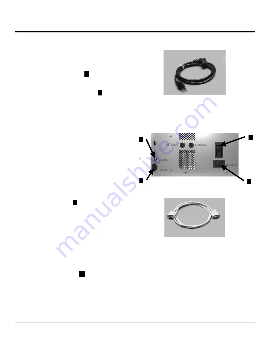
1. Make sure the power switch (
1
Figure 2-BB) is in the
off "O" position.
2. Plug the power cord (Figure 2-AA) into the power inlet
located on the rear of the instrument (
2
Figure 2-BB).
3. Plug the other end of the power cord into an
appropriate AC electrical outlet. The outlet should be
a dedicated line and it must be grounded.
4. Switch the Power Switch to the ON position
labeled "I".
NOTE:
Once the instrument is powered on it should
remain on unless the ink cartridge has been replaced by
the transport cartridge. This is done to prevent the print
head from drying out. See page 4.2 for control panel
power indications. Follow the instructions outlined on page
6.4 for removing and replacing the ink cartridge.
Setting up the Data Connection
A serial data cable is a standard accessory and is
required for the function of the printer.
1. Connect one end of the serial data cable (Figure 2-
CC) to the serial port (
3
Figure 2-BB) on the printer,
and the other end to one of the serial ports (COM 1,
COM 2) of the computer running the control software.
NOTE:
Be sure the outlet supplies the proper voltage and
frequency for the instrument. Refer to the rating label
(located at the rear of the instrument) to determine the
proper voltage rating.
Connecting a remote alarm device
If required, an external alarm system (not included)
may be connected to the printer. The remote alarm can be
connected to the printer jack (
4
Figure 2-BB) (via a 6.3
mm diameter jack connector (not included).
4
3
Figure 2-AA
Figure 2-BB
Figure 2-CC
1
2
Содержание Tissue-Tek Autowrite
Страница 1: ...3 4 2011 Tissue Tek Autowrite Slide Printer ...
Страница 18: ...1 14 Revised 3 04 11 INTRODUCTION ...
Страница 32: ...2 14 Revised 3 04 11 INSTALLATION SETUP ...
Страница 43: ...Revised 3 04 11 3 11 Section 3 ...
Страница 62: ......
Страница 68: ...8 2 Revised 3 04 11 SERVICE AND REPLACEMENT PARTS ...


