Functional unit workshop service
VHF 5000 System
3-40
0608
Reference
Operation/Test
Test Criteria
Comments/instructions
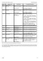
TIC-01
Power up radio
Pass:
Activity observed
Digital output from baseband board (Pin 16)
Fail:
Otherwise
Check signal is toggling when
activating/deactivating PTT.
Pass:
Activity observed
Digital output from baseband board (Pin 15)
Fail:
Otherwise
Check signal is toggling when
activating/deactivating PTT.
Pass: Signals high when
required.
Digital outputs from RF board.
Fail: Otherwise
• Pin 12 – RX lock detect shall be high
while receiving (measured 1 second after
PTT is released).
• Pin 14 – TX lock detect shall be high
while receiving (measured 1 second after
PTT is pressed).
• Pin 13 – DSC lock detect shall always
be high (measured 1 second after power-
)
Any system failure reporting wrong
frequencies in the display during normal
operations, are related to these signals.
Pass:
High on active PTT.
Fail:
Otherwise
Pass:
High on active PTT.
Fail:
Otherwise
Pass:
High on active PTT.
Fail:
Otherwise
Pass:
Activation observed.
Digital output from baseband board Pin 9).
Fail:
Otherwise
This signal is toggled by pushing the 1W
button on the transceiver front.
Pass:
High on active PTT.
Fail:
Otherwise
Pass:
Follow duplex channel
selections (high on duplex
channel).
Fail:
Otherwise
TIC-09
Power Valid
Digital output from RF board (pin 11). Shall
be high during transmission (measured 1
second after PTT is activated).
TIC-10
Duplex (RT5020 duplex
radio only)
Digital output from baseband board. The
duplex signal shall toggle if a channel shift
from a duplex to a simplex channel is
performed (or vice versa).
TIC-07
PA Key
Digital output from baseband board Pin 7).
TIC-08
Power 1W/25W
Digital output from baseband board (Pin 8).
TIC-06
High Tension
Digital output from baseband board Pin 6).
TIC-04
Lock Detects
TIC-05
PTT
TIC-02
SPI clock
TIC-03
SPI Data
Tabel 19 (TIC) - Transceiver interconnection control signal verification tasks.
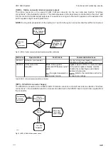
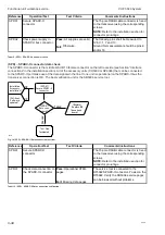
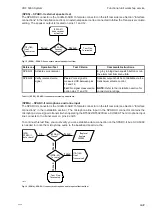
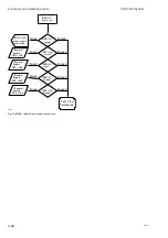
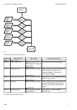
Control signals shall be verified before any AF signal path is checked (Transceiver interconnection control signal
flow). If any of the control signals are failing it makes no sense to continue the following check flow (Transceiver
interconnection AF flow).
Содержание RT5022
Страница 2: ......
Страница 4: ...VHF 5000 System 0930 ...
Страница 16: ...Maintenance VHF 5000 System 2 2 ...
Страница 70: ...Feature sales VHF 5000 System 4 2 ...
Страница 82: ...Installation VHF 5000 System 5 12 0608 ...
Страница 83: ...VHF 5000 System Installation 5 13 0608 ...
Страница 84: ......


