Functional unit workshop service
VHF 5000 System
3-18
0608
Configuring the Radio after replacement of the Base Band module
As all radio configuration and identity data resides on the Base Band module, it is necessary to configure a few
settings on the radio, after the base unit or the Base Band module has been replaced:
•
Serial number
must be set. The serial number of the radio is found on the identity tag on the rear bottom
side of the cover. The serial number set in the radio, must match the serial number displayed on the tag.
Important:
You must program the serial number correct the first time. It can only be programmed once.
•
Radio Type
. The radio type must be set to either simplex or duplex according to the actual hardware.
“Simplex” must be selected for an RT5022 Simplex type, and “Duplex” must be selected to configure the
software to control a duplex radio.
The settings are entered using the SB5006 service tool. Please consult the SB5006 operations manual (e.g.
Part 5 in this manual) on how to program “System Parameters”.
If the service interface is able to run with the RT50XX unit before repair, it will be possible to save the radios
original user-specific settings (channel settings, contact list, etc.), before base unit/Base Band module is
replaced.
After the repair has been done, any saved configuration parameters can be copied back to the radio.
NOTE:
The System Parameters (e.g. serial number) are not part of the configuration parameters that can be
automatically copied.
3.2.12
Removing/installing the RF module of the VHF transceiver unit.
40463
(Replace)
replace
PCB or PA
(MPC-Flow)
module
power
(TIC-Flow)
transceiver
control
(TIAF-flow)
transceiver
audio
Rx/Tx
antenna
(DSCA-flow)
DSC antenna
(RTA-flow)
module
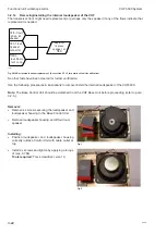
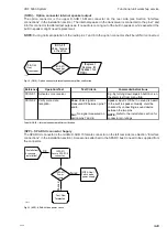
Fig. 4 RF or PA module replacement. (See section 3.2.15 for details on fault identification)
The antenna check flows (RTA and DSCA) might point on problems with the RF module. The connection
between antennas and RF module are located under the Base Band module. Therefore the Base Band module
must be removed before the antenna connection can be checked.
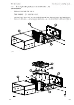
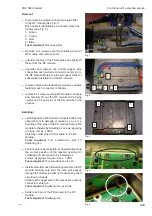
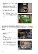
Use the following procedures & illustrations to remove/install the RF module. The sequence of the procedures
applicable to the removal and the installation respectively is consecutively numbered 1 through 6 and should
be carried out in accordance with this.
Note:
In case of the RT5022 simplex/semi duplex VHF step 1) for “Removal” and step 6) for “Installing” in the
following procedure, does not apply.
Tests that have lead to the replacement of either RF module or the Power amplifier module (PA) are listed in
the following figure.
Содержание RT5022
Страница 2: ......
Страница 4: ...VHF 5000 System 0930 ...
Страница 16: ...Maintenance VHF 5000 System 2 2 ...
Страница 70: ...Feature sales VHF 5000 System 4 2 ...
Страница 82: ...Installation VHF 5000 System 5 12 0608 ...
Страница 83: ...VHF 5000 System Installation 5 13 0608 ...
Страница 84: ......


