Functional unit workshop service
VHF 5000 System
3-20
1007
Fig. 6
Fig. 7
Fig. 1
1
2
3
4
Fig. 2
•
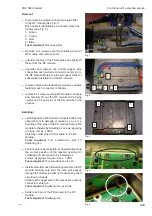
Position the shielding cover correctly over the RF
module.
Install all 10 x screws loosely followed by tightening
the outermost 4 screws in the order indicated in the
illustration, applying a torque of max. 0.7Nm.
Tighten the remaining 6 x screws applying a torque
of max. 0.7Nm.
Using same sequence further tighten the 10 screws
applying a torque of max. 1.0Nm.
Tools required:
Torx screwdriver, size 10.
•
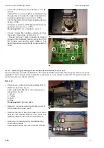
Connect duplex filter cabling according to their
respective colour code – refer to Fig. 2
- Ensure that each cable connector is seated
properly in its respective mating connector of the
RF module and position each cable in the
appropriate cable groove of the RF module shielding
cover.
Removal:
•
Disconnect 4 x cables connecting duplex filter to
the RF module (See Fig. 1).
Each cable is identified by a coloured sleeve as
follows (See Fig. 2):
1. Green
2. Yellow
3. Red
4. Blue
Tools required:
Flat nose pliers
•
Remove 10 x screws securing shielding cover of
RF-module and remove cover.
•
Unsolder the pins of the PA module and lift these
from the RF module Remove and retain the
(glasflex) insolation from each PA module pin.
•
Remove 4 x screws securing the BB-shielding
cover to the chassis.
Carefully lift and remove cover from BB module.
3.2.13
Removing/installing the PA module of the VHF transceiver unit
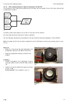
Use the following procedures & illustrations to remove/install the PA module. The sequence of the procedures
applicable to the removal and the installation respectively is consecutively numbered 1 through 5 and should
be carried out in accordance with this.
Содержание RT5022
Страница 2: ......
Страница 4: ...VHF 5000 System 0930 ...
Страница 16: ...Maintenance VHF 5000 System 2 2 ...
Страница 70: ...Feature sales VHF 5000 System 4 2 ...
Страница 82: ...Installation VHF 5000 System 5 12 0608 ...
Страница 83: ...VHF 5000 System Installation 5 13 0608 ...
Страница 84: ......


