VHF 5000 System
Functional unit workshop service
3-17
Removal:
•
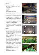
Remove 4 x screws securing the BB-shield to
the chassis. (See Fig. 1)
Carefully lift and remove shield from
BB module.
•
Disconnect all cables connected to the BB-module.
Remove 2 x screws securing the audio power
amplifier IC against the heatsink through the
retaining plate.
Remove two screws positioned in opposite
corners of the BB module securing this to the
chassis.
Carefully lift out the BB module from the
chassis.
Tools required:
Torx screwdriver, size 10
Installing:
•
Disconnect all cables connected to the BB-module.
Remove 2 x screws securing the audio power
amplifier IC against the heatsink through the
retaining plate.
Remove two screws positioned in opposite corners
of the BB module securing this to the chassis.
Carefully lift out the BB module from the
chassis.position the BB module correctly in the
transceiver chassis.
Secure by installing two screws in opposite corners
of the BB module, applying a torque of max. 0.7Nm.
Install retaining plate on top of audio power amplifier
IC and secure this against the heatsink by tightening
2 x screws, applying a torque of max. 1.0Nm.
Connect cabling.
•
Position the BB-shield correctly over the BB module.
Be careful in this process not to cause any damage
to the copper grounding strip at tached to trans-
ceiver heatsink Install 4 x screws loosely.
When ready to tighten screws gently press the BB-
shield against the pc-board and against the
grounding strip/heatsink.
Tighten the 4 screws in the sequence indicated by
the numbering (See Fig. 1), by applying a torque
of max. 0.7Nm.
Tools required:
Torx screwdriver, size 10.
Fig. 2
Fig. 3
2
1
3
4
Fig. 1
0608
Содержание RT5022
Страница 2: ......
Страница 4: ...VHF 5000 System 0930 ...
Страница 16: ...Maintenance VHF 5000 System 2 2 ...
Страница 70: ...Feature sales VHF 5000 System 4 2 ...
Страница 82: ...Installation VHF 5000 System 5 12 0608 ...
Страница 83: ...VHF 5000 System Installation 5 13 0608 ...
Страница 84: ......


