GB
13
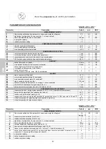
COMPRESSOR ADJUSTMENT
r0
adjuster hysteresis (differential)
+2 °C
1
15
r1
min. operating setpoint selectable
-25 °C
-40
r2
r2
max. operating setpoint selectable
-15 °C
r1
+99
COMPRESSOR PROTECTION
C0
compressor activation delay from device start
1 min
0
240
C2
min. delay between compr. stop and subsequent start
3 min
0
240
C5
compressor start cycle time in the event of room probe alarm
10 min
1
240
C6
C5 % where compr. starts in the event of room probe alarm
70 %
0
100
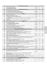
DEFROST
d0
defrost interval (0= excluded)
0 hours
0
99
d1
defrost type (0= resistance, 1= hot-gas)
0
0
1
d2
end-of-defrost temp. (relating to evaporator temper.)
+12 °C
-40
+99
d3
max. defrost duration (0 = the defrosting function will not start; 255 = the defrosting function will go
on continuously)
255 min
0
255
d6
defrosting display (0=actual cell temperature, 1=stopped cell temperature, 2=dEF label)
1
0
2
d7
dripping time
4 min
0
15
dE
defrost interval count: 0= actual hours; 1=hours comp. ON; 2= autodeterm.
0
0
1
ALARMS
A0
alarm hysteresis (differential)
+2 °C
1
15
A1
min. operating setpoint alarm (0= excluded)
-2 °C
-40
0
A2
max. operating setpoint alarm (0= excluded)
+15 °C
0
+99
A3
alarm exclusion from device start
120 min
0
240
A4
buzzer activation mode for alarm : 0= always; 1= timer-controlled
1
0
1
A5
time limit for buzzer acoustic signal (only if A4 = 1)
20 s
0
240
A6
temperature alarm exclusion time (only if A1 and/or A2 0)
15 min
0
240
A7
temp. alarm exclusion time after evap. stop (for A1 and/or A2 0)
60 min
0
240
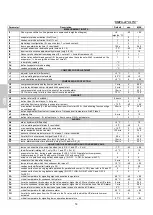
ADJUSTING THE EVAPORATOR AND CONDENSER VANS
F1
temper. above which the evap. fan stops ( only if /A = 1 and F7 = 3 or 4)
-1 °C
-40
+99
F2
fan differential (relating to F1, only if /A = 1 and F7 = 3 or 4)
+2 °C
1
15
F3
evaporator fan func. during regular operation (0=OFF; 1=ON; 2=parallel with compressor;
3=determined by F1 and F2 with comp. ON and OFF with comp. OFF
2
0
4
F4
evap. vent. operation during defrost and dripping (0= OFF, 1= ON, 2= determ. with F7)
0
0
2
F5
evaporator fan stop after dripping
3 min
0
15
F6
temperature below which the condenser fan turns off
10 °C
-40
+99
F7
condenser fan differential (relating to F6)
+3 °C
1
25
F8
condenser fan func. during regular operation (0=parallel with compr.; 1=ON); also refer to F6 and F7
0
0
1
F9
condenser fan func. during defrost and dripping (0=OFF; 1=ON, 2=ON if Tc≥26°C and OFF if
Tc<25°C)
2
0
2
FA
critical temperature for signalling high condensation temperature
46 °C
-40
+99
Fb
critical temperature for condenser dirty alarm
48 °C
-40
+99
Fc
time the condenser probe stays on the value equal or higher than FA for activation of the HtC alarm
5 min
0
240
Fd
time the condenser probe stays on the value equal or higher than Fb for activation of the dCA alarm
1 min
0
240
FE
temperature increase on the device set point value in case of an active dCA alarm
5 °C
1
15
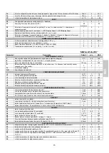
FF
critical temperature for high pressure alarm
55 °C
-40
+99
FH
time limit used to pass from the FA value to the Fb value, within which the HP alarm is however
activated
12 s
0
15
FL
critical temperature for signalling low evaporation temperature
-37 °C
-40
+99
Fn
time the evaporator probe stays on the value equal or higher than FL for activation of the LtE alarm
30 min
0
240
Fo
time the LtE alarm stays, upon reaching of which automatic defrosting is forced
30 min
0
240
FP
critical temperature for low pressure alarm
-41 °C
-42
+99
P0
Configuration parameters printing enable (0 = disabled)
1
0
1
P1
Sampling time (see also parameter P6)
60
min/hours
1
60
P2
Selection of temperature probe to be printed (0 = none, 1=chamber probe, 2 = chamber and
evaporator probe)
1
0
3
P3
Payslip heading selection (0 =excluded, 1 = BTV Display Case, 2 = BTS Display Case)
2
0
2
P4
Equipment identification number printing enable (0 = no, 1= yes)
1
0
1
P5
Selection of language for payslip heading (1=Italian, 2=English, 3=French, 4=Spanish, 5=German)
1
-1
5
P6
Selection of unit of measure for sampling time (1 = minutes, 2 =hours)
1
1
2
COMMUNICATIONS MANAGEMENT
L1
Instrument address (date detected in printing phase if P4 = 1)
1
0
255
L2
Serial port management (o = not utilised, 1 = print)
1
0
1
L3
Baud Rate data transmiss. (1=2400, 2=4800, 3=9600, 4=18200)
3
1
4
L4
Transmission control mode (0 = no parity, 1 = odd, 2 = even)
0
0
2
Содержание C8Q
Страница 10: ...IT 8 CARATTERISTICHE TECNICHE Le dimensioni degli apparecchi sono riportati di seguito 184 184...
Страница 28: ......
Страница 36: ...FR 8 CARACTERISTIQUES TECHNIQUES Les dimensions des appareils sont report es ci dessous 184 184...
Страница 54: ......
Страница 62: ...DE 8 TECHNISCHE EIGENSCHAFTEN Die Ma e der Ger te sind die folgenden 184 184...
Страница 80: ......
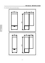
Страница 88: ...GB 8 TECHNICAL SPECIFICATIONS The dimensions of the units are found below 184 184...
Страница 106: ......
Страница 114: ...ES 8 CARACTERISTICAS TECNICAS Las dimensiones de los equipos se encuentran a continuaci n 184 184...
Страница 132: ......
Страница 140: ...NL 8 TECHNISCHE KENMERKEN De apparaten hebben de volgende afmetingen 184 184...
Страница 159: ...RU 1 2 2 2 3 4 8 9 10 SMART FUNCTIONS 10 11 11 11 16 17 17 21 22 22 22 22 23 23 23 24 25...
Страница 160: ...RU 2 Gelateria 25 15 C HFC Z Z Y 1 2 3 4 5 N 6 B C D E F G H L R W...
Страница 161: ...RU 3 OFF...
Страница 162: ...RU 4 12...
Страница 163: ...RU 5 A B C A B C A A A B C B C C B...
Страница 164: ...RU 6 10 5 min 10 cm min 5 cm min 5 cm 4 T 30 C 55 72...
Страница 165: ...RU 7 SHUKO N60320...
Страница 166: ...RU 8 184 184...
Страница 177: ...RU 19 on sby enter on sby enter on sby enter on sby enter rES on sby enter bLO on sby enter on sby enter rES dA 10 HtC...
Страница 178: ...RU 20 22 C 5 C 25 C 15 C HtC 22 C 5 C 25 C 15 C dCA HP stand by HP 22 C 5 C 25 C 15 C LtE...
Страница 180: ...RU 22 3 Sby OFF OFF...
Страница 181: ...RU 23 1 2 30 OFF...
Страница 182: ...RU 24 2002 96 EC 2002 96 WEEE WEEE 2002 96...
Страница 192: ...P 8 CARACTER STICAS T CNICAS As dimens es dos aparelhos s o relatadas a seguir 184 184...

