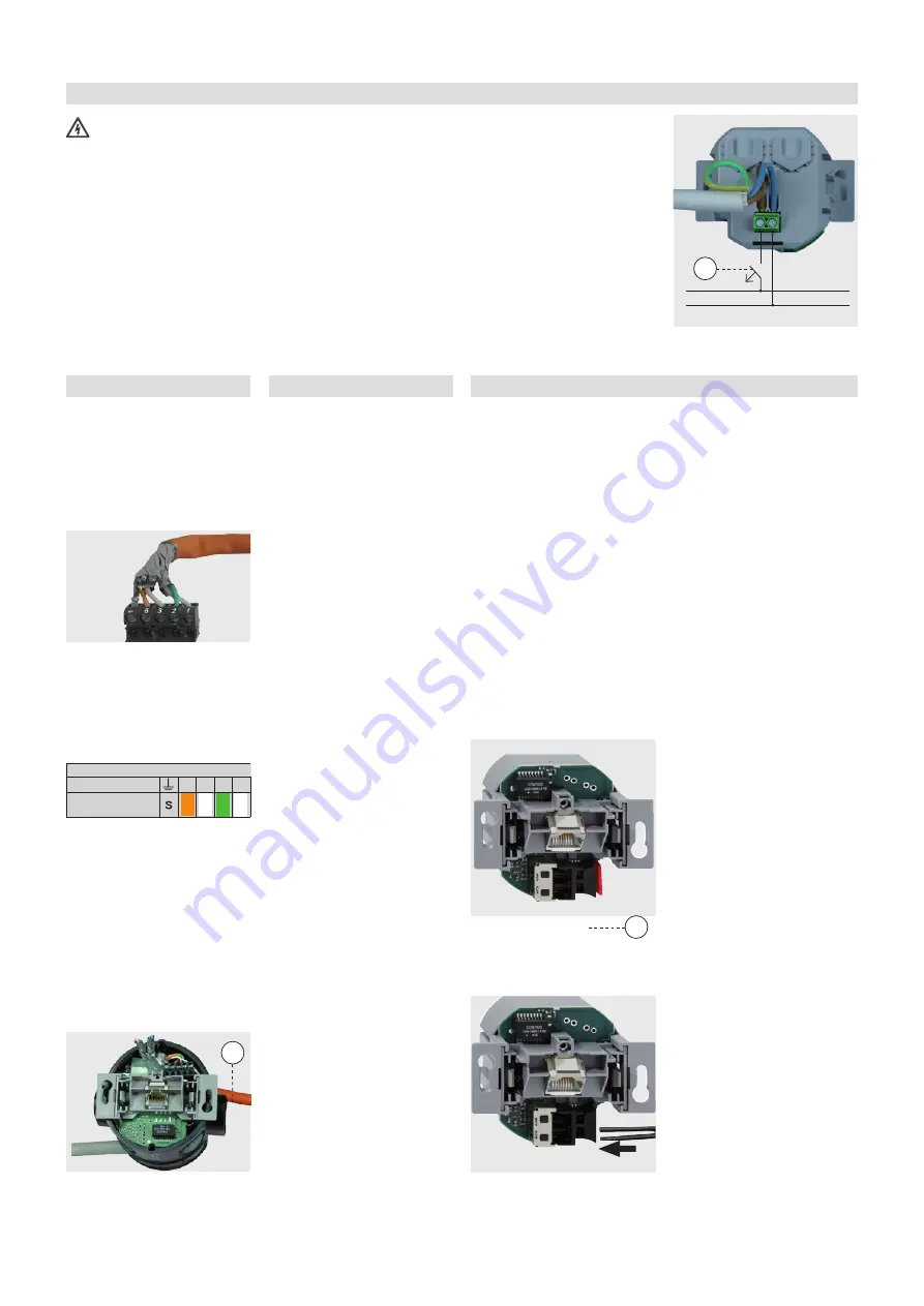
6 Installation
Installation
Connecting the supply voltage
Caution: Risk of death!
Disconnect the power
supply before making
the connections!
When working in and on electri-
cal systems, follow the five safety
rules according to DIN VDE 0105:
1 Disconnect the power.
2 Secure against restarting
3 Verify that there is no voltage
on all poles.
4 Ground and short-circuit
5 Cover neighboring parts that
are still live.
Connect the power supply
according to the figure on the
right. To prevent malfunctions/
changes in the 230 V system from
affecting the network, always sep-
arate the power supply to active
components and to the data end
devices (PC, etc.) from the power
supplies to other consumers (e. g.
microwave ovens, vacuum clean-
ers, radios, etc.).
Use separate circuits by inserting
a line disconnector or line protec-
tion switch (Figure, A), and pos-
sibly by inserting suitable surge
protection (Class C). Clearly mark
the circuit as well as the associ-
ated sockets, e.g. with the label
„IT““.
Connecting the network cable
1 It is best to pull the cable into
the wall box from the top
(Figure, B). Use
device
junction boxes
only!
2 Cut the cable so that there
are about 90 mm extending
past the bottom of the junc-
tion box.
3 Remove about 80 mm of insu-
lation from the cable.
4 Place the AC WLAN in the
flush-mount box.
5 Pull off the 5-pin screw terminal
block and connected the wires
according to the color codes.
• Leave the wire pair shield-
ing on and the wires
twisted for as long as
possible!
• Twist the cable shield (S)
together and use a
1 mm wire end sleeve, if
necessary.
• Make sure the wires are
connected in the same
manner on the patch
panel and on the jack!
6 Place the terminal block on
the screw terminal.
7 Check the installation based
on the LED‘s (see „Meaning
of the LED‘s“ on page 6) and
mount the cover.
Initial Configuration
It is recommended to set up the
initial configuration over the LAN
interface of the device, for exam-
ple using the socket on the front.
Connect the LAN interface of your
PC to AC WLAN to configure it.
The factory settings require
address of the PC to be within
the address range 192.168.0.xxx
(x ≥ 0 ≤ 255, x ≠ 5 !). Subnet
mask: 255.255.255.0
1 Start your web browser (e.g.
the Internet Explorer) and
enter http://192.168.0.5 in the
address line. The AC WLAN
then sends a message asking
you to enter the password. In
the factory settings, the pass-
word is „admin“.
2 Configure the AC WLAN as
desired.
3 If it is only possible to specify
the initial configuration over
the WLAN, then you must first
search for the AC WLAN in
the wireless interface of the
device to be used (tablet PC
or a similar device). The AC
WLAN appears in the network
using the SSID „Rutenbeck“.
The factory setting for the
WLAN password is „wire-
less123“.
When changing the SSID,
use standard letters and
numbers only.
The WLAN IP address of the
device used for programming
must be within the address
range 192.168.0.xxx (x ≥ 0 ≤
255, x ≠ 5 !). Subnet mask:
255.255.255.0
4 Configure the AC WLAN as
desired.
Cutting and connecting the POF cable
1 After installing the POF cable
(you will find information on
this topic at www.rutenbeck.
de in the download section),
proceed as follows:
2 Pull the cable into the switch
or channel installation box
and shorten the fiber-optic
conductor to about 190 mm.
Use
device junction boxes
only!
3 Carefully split the cable in the
middle for about 30 mm and
make sure that there are no
bumps on the sheath that
could prevent you from insert-
ing the cable.
4 Insert it in the POF cutting tool
and cut it by pressing on the
blades.
5 Make sure that both conduc-
tors are the same length.
6 Open the POF terminal
by pulling lightly on the black
connector and remove the
red protection cap (C).
7 Insert the AC WLAN in the
flush-mount box.
8 Insert the POF cable (the
arrow in the figure) and make
sure that you push it in up to
the stop in order to ensure a
good connection.
9 Close the POF terminal by
pushing the black connector
into the device opening to
fasten the cable in place.
10 Now connect the AC WLAN
to the LAN interface of your
PC using a patch cable and
configure it as desired.
11 Check the installation based
on the LED‘s (see “Meaning of
the LED‘s” on page 6).
12 Mount the cover.
Installation
6 3 2 1
Color Code
Terminal
Connection
B
C
L
N
A


