RTD Embedded Technologies, Inc.
| www.rtd.com
48
DM35418HR/DM35218HR
User’s Manual
BDM-610010041 Rev F
6.5.15
CH
N
_FIFO_DATA_CNT
(R
EAD
)
This register shows the current sample count that is available in the ADC channel FIFO.
6.5.16
CH_INT_STAT
(R
EAD
/C
LEAR
)
This is the status register for the channel interrupts. Reading a value of ‘1’ indicates that an event has occurred. Reading a value of ‘0’ indicates
that the event has not occurred. Writing a ‘1’ will clear that bit.
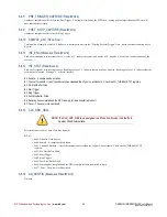
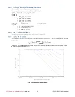
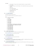
The upper eight bits of the DAC value can be used for Markers. These Markers can be used to generate an interrupt when a certain part of the
waveform is sent to the DAC. This allows an automated indication to the application software as to the state of the data being sent to the DAC.
Marker bit 7 corresponds to bit 31 of the DAC data, and Marker bit 0 corresponds to bit 24 of the DAC data.
B0: Marker 0
B1: Marker 1
B2: Marker 2
B3: Marker 3
B4: Marker 4
B5: Marker 5
B6: Marker 6
B7: Marker 7
6.5.17
CH_INT_ENA
(R
EAD
/W
RITE
)
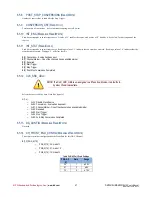
These are interrupts enables for the Data Markers. Bit defines are above.
6.5.18
CH_LAST_CONVERSION
(R
EAD
/W
RITE
)
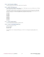
The last value sent to the DAC Converter.
B[31:24]: DAC Markers
B[15:0]: DAC Data
If the current Mode is “Reset” or the associated DMA engine is set to “Clear”, a write to this register will immediately update the DAC
Converter.

