


RTD Embedded Technologies, Inc.
| www.rtd.com
28
DM35418HR/DM35218HR
User’s Manual
BDM-610010041 Rev F
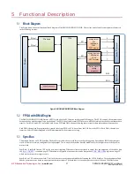
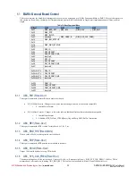
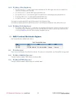
SyncBus3 to synchronize all the boards set as inputs, or slaves. Once boards are synchronized the
register will be set to ‘1’
indicating it is now stable and ready to use.
NOTE: Only enable one output per SyncBus line when synchronizing
multiple boards. Enabling multiple outputs on a SyncBus line will
result in unexpected behavior.
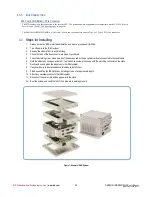
5.4
Digital I/O
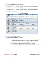
This module provides 32-bits of bi-directional digital I/O. Each bit is programmable as either an input or output. On power cycle, all digital I/O
lines are programmed as inputs, meaning that the digital I/O line’s initial state is undetermined. If the digital I/O lines must power up to a known
state, an external 10 kΩ resistor must be added to pull the line high or low.
section on page 49 for more information on register configuration.
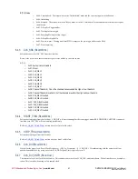
5.5
Temperature Sensor
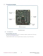
This module provides an on board temperature sensor. This sensor provides the module’s ambient temperature. Refer to
figure on page 14 for temperature sensor location.
The temperature sensor provides a signed 12-bit value that capable of measuring temperatures within ±2°C. The temperature sensor is read
continuously, approximately every 1 to 2 seconds. This value is then automatically updated in the register. Refer to
section on page 50 for more register information.
5.6
Analog input
The DM35418HR/DM35218HR has 4/8 independent 18-bit SAR ADC converters, to provide high speed and high digital resolution of the analog
input. The ADC converter has a max throughput of 1.5MHz per channel. The high input impedance, low distortion, low noise operation design
gives you accurate results. This module also provides ±28V overvoltage input protection to the analog connector (CN4).
The DM35418HR/DM35218HR has a programmable input. This provides the user the ability to select single-ended/differential input, full-scale
input range, and unipolar/bipolar input.
Each ADC converter supports a 511 sample FIFO for DMA. Each sample packed into a 32-bit word.
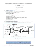
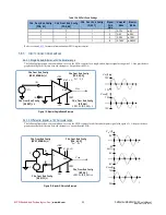
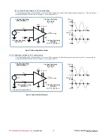
Single-Ended Input Mode
In single-ended mode, the input signal is measured in reference to the boards GND. In this mode the input signal is connected to input ADC0.0+
through ADC1.0+, and the low side to any of the GND pins available on the Analog Connector.
Differential Input Mode
In this mode your signal source may or may not have a separate ground reference. In differential mode, the high side input is measured in
reference to the low side input. In this mode you connect the high side of the input signal to the analog input, ADC0.0+
through
ADC7.0+, and
connect the low side to corresponding ADC
-
pin. When in differential mode, both the high and low side must stay /-10V with respect to
the board ground. In most cases, the board ground must still be attached to the device that is generating the input signal.
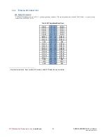
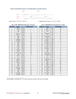
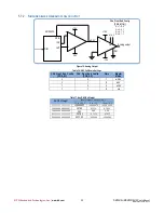
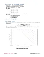
Full-Scale Input Range
The DM35418HR/DM35218HR has a programmable gain input per channel. This gain can be programed for 1,2,4,8 to achieve input ranges
±
5V,
±
2.5V,
±
1.25V,
±
0.625V.
Refer to
on page 29 for full-scale ranges for both unipolar and bipolar modes.
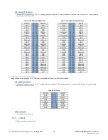
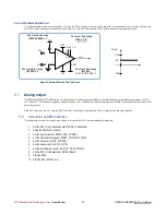
Bipolar/Unipolar Mode
In bipolar mode the data is collected in two’s complement format. In this format the MSB of the data is the sign bit. If the MSB is “0” the output
data is positive value. If the MSB is “1” the output code is negative. The 18-bits of data is sign-extended into a 32-bit word before transferring to
the FIFO.
In unipolar mode there is no sign bit, since all values are positive. When the output code is all “0” the input voltage is 0 volts. When the output
code is all “1” the input voltage is 10 volts when the gain is set to 1.


