5
x
Operation
34
FA ROTEX Solaris RPS3 P2 - 06/2012
5.3.1 Start display
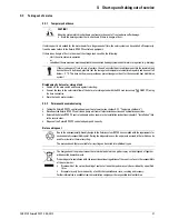
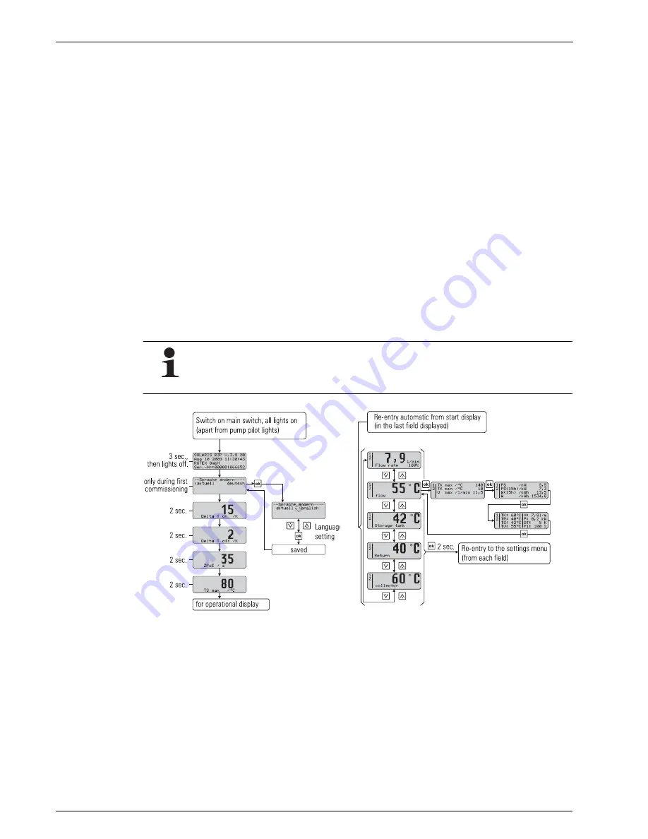
After switch-on, the Solaris R3P control system runs a self-test, during which the display elements are actuated and the
setting parameters of the user level are displayed. The following test steps are run and displayed in succession for approx. 2 s
(image 5-7):
– Immediately after switch-on the start screen appears showing the installed software version and the serial number of the
unit.
– At the initial start-up the user is prompted to select the display language.
– The functions of the pumps and the status indicators can only be checked manually for security reasons (see chapter 5.2.3).
5.3.2 Operating display
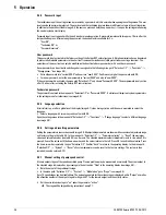
The operating display shows system temperatures, maximum and calculated values. After the start display the Solaris R3P
control systems are automatically in operating display mode, an operating value is displayed and the associated indicator
lights up.
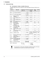
• Press the arrow keys to navigate through the four temperature measured values and the flow value (see table 5-2 and
table 5-6).
• Press the Info button to show the maximum and calculated values (see table 5-3).
The left column of the display is the status display. This means:
– "1" in the first line, tank circulation pump P1 active.
– "2" in the second line, solar panel circulation pump P2 active.
– "B" in the third line, burner inhibit contact active (see chapter 5.3.9) or a fault status (see chapter 6.2).
– "H" in the fourth line, manual mode active.
5.3.3 Settings menu
The parameters of the Solaris R3P control systems are displayed and modified in this menu.
• Press once (>2 s) on the OK pushbutton to open the menu or to return to the operating display. Press briefly to confirm a
selection, open the next menu display or "Saved" is shown for approx. 1 s if a value is changed.
• In the required parameter display press OK to open parameter change mode.
In the menu (image 5-9) the active menu path is displayed in the first line, a cursor (">") in the left column indicates the next
lower menu path or a parameter. Then use the arrow keys to scroll up (+ pushbutton) or down (– pushbutton) in the menu tree.
The set value can be modified with the arrow keys.
A short press on the arrow key changes the value one step, press and hold to make larger changes.
So long as no manual adjustments are made or an event corresponding to table 6-2 produces a different
display, the actuated measured value or information display remains active. It is also reactivated after
parameter changes or switching off and on. If information values are displayed, no measuring point indicator
light is activated.
Fig. 5-7
Start display
Fig. 5-8
Operating display


