background image

x

 Operation

37

FA ROTEX Solaris RPS3 P2 - 06/2012

5.3.8 Correction values for measuring points

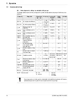
If the measured value of a sensor deviates from the actual value, it can be compensated with a correction value.

• In the menu path: "Selection 2/2" -> "System" -> "Correction values" select the correction parameter (see image 5-9) and 

modify values table 5-4 accordingly.

Table 5-4 Correction values

5.3.9 Burner inhibit contact

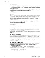
This contact controls an external heat generator so the storage tank is not heated by the external heat generator under favourable 
weather conditions. The connection cable offered as an accessory (

16 41 10

) is required. If the solar system reaches an 

instantaneous output (adjustable by the technician) (menu path: "Selection 1/2" -> "Parameter selection" -> "Operating 
parameter "P min"") or if the storage tank is heat to a minimum tank temperature (adjustable by the heating expert) (operating 
parameter "TS min" see table ), the burner is disconnected from the power by contact. The setting of the burner inhibit contact 
is described in image 5-9.

The cut-in time for the burner inhibit contact can be set to a delay with the parameter "VBSK". The burner inhibit contact only 
switches on after a defined delay time when the minimum storage tank temperature "TS min" is exceeded or if the defined 
minimum instantaneous output for the burner stop "P min" is exceeded (for example see image 5-10).

Name

Access level

Measurement & 

adjusting range

Factory setting

Step width

Solar panel temperature correction

Technician

-9 to +9

0 K

1 K

Return temperature correction

-9 to +9

0 K

1 K

Storage tank temperature correction

-9 to +9

0 K

1 K

Feed temperature correction

-9 to +9

0 K

1 K

Flow correction

-2 to +2

0 l/min

1 l/min

Explanation:
The limit value "TS min" is not reached or is exceed within time "VBSK". The burner inhibit contact was not activated immediately but only 
after the limit value "TS min" was not reached or was exceeded and after expiry of the defined time "VSBK"

Fig. 5-10 For example: function of delay time on triggering the burner inhibit contact

Содержание Solaris RPS3 P2

Страница 1: ...r atur max zul ssige r Betrie bsdru ck im Edel stahl W r meta usche r Daue rleistu ng DIN 4708 Leistu ngske nnzah l DIN 4708 aber maxim al Ladel eistun g Speic her 65 C Kaltw asser 10 C Warm wasse r 4...

Страница 2: ...laris RPS3 P2 pressurised solar system used in conjunction with pressure station RDS1 We ROTEX Heating Systems GmbH declare under our sole responsibility that the products Product Order No Product Ord...

Страница 3: ...out of service 23 4 1 Initial start up 23 4 1 1 Fill solar panel circuit 23 4 1 2 Filling storage tank circuit system without FlowSensor 25 4 1 3 Filling storage tank circuit system with FlowSensor 26...

Страница 4: ...4 3 Recommended setting for supplementary heating with external heat sources or the electric immersion heater burner inhibit contact 40 5 4 4 Tips for optimised user behaviour 41 5 4 5 Domestic water...

Страница 5: ...the installation instructions included for the applicable installation type When connecting to an external heat generator or storage tank which is not included in the scope of delivery the individual...

Страница 6: ...is the case for example with genuine spare parts 1 5 Instructions for working safely Working on the roof Installation work on the roof may only be carried out by authorised and trained persons heating...

Страница 7: ...ar flow layered pipe 15 Corrugated stainless steel heat exchanger for heating support 16 Thermal insulation of stainless steel heat exchanger for heating support 17 Connection solar return flow 18 Imm...

Страница 8: ...ed as storage tanks for the ROTEX solar system ROTEX Sanicube Solaris Thermally insulated non pressurised plastic storage cylinder ROTEX Hybridcube Thermally insulated non pressurised plastic storage...

Страница 9: ...pressure gauge installation accessories Fig 2 3 RDS1 pressure station RPWT1 16 20 31 For connecting the RDS1 pressure station to an unpressurised hot water storage tank Heat output 6 kW For pressuris...

Страница 10: ...wSensor supplied with 3 m cable FLG 16 41 07 For regulating the flow volume Consists of FLG FlowGuard 2x seals Fig 2 7 FLG FlowGuard MAG S 25 16 20 50 For ROTEX Solaris pressure systems with up to 3 s...

Страница 11: ...1 ROTEX recommends this connection type Fig 3 2 Solar panel with connections on same side with Sanicube hot water storage tank WARNING Live parts can cause an electric shock on contact and cause fata...

Страница 12: ...lanking plug on the installation side Insert the combined filling and draining cock in the installation side and secure it with the retaining clip again 5 Fit the preassembled pump unit on the storage...

Страница 13: ...e press fitting on the pump outlet pipe Fig 3 12 Work step 11 Fig 3 13 Work step 12 CAUTION In the case of longer pipe runs with only a minimum gradient it is possible for water pockets with a siphoni...

Страница 14: ...of scalding if incorrect connection pipes are used Use only connection pipes made of pressure resistant metal Cu 22 mm recommended between the solar panels and the hot water storage tank Plastic pipe...

Страница 15: ...nger connection set Replace outside cover 1 Installing the clamping ring bolt Cut off the pipe end at right angles and debur Place swivel nut and clamping ring on the pipe Lightly oil threads Push pip...

Страница 16: ...connect the junction box of the domestic electrical installation 3 Remove cover on switch casing of solar panel circulation pump 4 Install control line from solar panel circulation pump to Solaris RPS...

Страница 17: ...front under the control system housing to form an even join all around the control systems 9 Screw front of casing on both sides to the control systems housing with countersunk screws Fig 3 22 Work st...

Страница 18: ...iler control must never be immersed more than 75 cm into the sensor immersion sleeve If the storage temperature sensor is immersed any deeper the hot water zone may overheat and cause the boiler contr...

Страница 19: ...ts the passing flow during operation 1 Place seal b on the solar flow connection a of the hot water storage tank 2 Screw FlowSensor c to the solar flow connection a of the hot water storage tank 3 Pla...

Страница 20: ...S3 P2 control and pump unit image 3 43 Operation The solar return flow from the RPWT1 plate heat exchanger comes from the solar zone of both storage tanks via the return flow connection line image 3 4...

Страница 21: ...ised area 3 Pressure area 4 Solar panel 5 Return flow connection pipe non pressurised area 6 Solar flow distribution pipe 7 Solar return pipe 8 Solar flow pipe DH Level difference in non pressurised s...

Страница 22: ...t on the connecting t piece 12 Position the flat gaskets on the two FlowGuards and fasten both FlowGuards to the inflow connection line with the swivel nut 13 Position seal on the connecting t piece a...

Страница 23: ...r medium is mixed with other substances frost and corrosion protection may be reduced This may damage system components Conduct all work on the components of the solar system only with the solar panel...

Страница 24: ...uit pressure to at least 0 3 bar above the pressure set at the diaphragm expansion vessel MAG see system fill pressure tab 4 1 12 Close upper filling and draining cock 13 Vent the system as follows Di...

Страница 25: ...he fill level Switch on Solaris RPS3 P2 control and pump unit again initialisation phase begins When the initialising phase is finished temperature display you can start the manual operating mode by s...

Страница 26: ...e initialising phase is finished temperature display you can start the manual operating mode by simultaneously pressing both arrow keys Measure the time until the inflow is heated at the plate heat ex...

Страница 27: ...t correctly Notes on disposal CAUTION A heating system which is shut down can freeze in the event of frost and may suffer damage Drain the heating system that is shut down if there is danger of frost...

Страница 28: ...Solar panel circulation pump P2 lit when pump is in operation 9 Up arrow for moving the temperature or parameter display up by one setting increasing parameter settings 10 Down arrow for moving the t...

Страница 29: ...flashes The lock out time Time SP function allows the pumps to be released again in a shutdown condition caused by the feed sensor FlowSensor only after expiry of the lock out time set in the Solaris...

Страница 30: ...heating expert a fault signal is not shown The control system now operates without the measured value for the flow The feed temperature TV is set to be equal to the solar panel temperature TK 5 2 5 Ou...

Страница 31: ...refore the flow through the solar panels is increased until the nominal spread is reached If the spread is too low the pump output is reduced The actual pump output of P1 while it is running is displa...

Страница 32: ...s or vapour formation in the storage tank circuit or a leak in the storage tank circuit To prevent all buffer water from being pumped out of the system if there is a leak both pumps are shutdown for 2...

Страница 33: ...measuredsolar panel temperature 30 to 250 C 1 K none V max Maximum flow 0 0 to 12 0 l min 0 1 l min Maximum flow that was reached during filling with FlowSensor 12 0 0 to 20 0 l min Maximum flow that...

Страница 34: ...first line tank circulation pump P1 active 2 in the second line solar panel circulation pump P2 active B in the third line burner inhibit contact active see chapter 5 3 9 or a fault status see chapter...

Страница 35: ...through to the bottom the user is returned to the selection menu Selection 2 2 and then to the operating display see image 5 9 The control system now operates immediately with the modified parameter...

Страница 36: ...important systems parameters in the settings menu for technicians see image 5 9 5 3 5 Language selection At initial start up or after a global reset the display image 5 7 stops during start up and the...

Страница 37: ...the burner is disconnected from the power by contact The setting of the burner inhibit contact is described in image 5 9 The cut in time for the burner inhibit contact can be set to a delay with the p...

Страница 38: ...s TK max Booster temperature maximum solar panel temperature i x 20 to 110 C 75 C 1 K TK zul Cut in protection temp max approved operating solar panel temp i x 90 to 250 C 110 C 1 K TR min Minimum tem...

Страница 39: ...system to switch on again only in the late afternoon although the storage tank temperature allows additional heating To maximise the energy input set the cut in protection temperature parameter to a v...

Страница 40: ...ating control generates a heat requirement Set the operating parameter P min TS min and VBSK see chapter 5 3 9 so the external heat generator does not heat if the solar panels generate a minimum heat...

Страница 41: ...er minute means a reduced requirement for supplementary heating and therefore more hot water at a higher temperature Reduce draw off times Lower energy consumption When filling the bathtub use only ho...

Страница 42: ...or values remain accessible via the arrow keys Event code Plain text display Description Status display flashing Lamp flashing Consequence 0 Collector Solar panel sensor short circuit or interruption...

Страница 43: ...sponding to start phase V1 table 5 1 was not reached at the FlowSensor The system is temporarily blocked for 2 h and then automatically attempts to start Sensor Cause of the fault Status flashes Displ...

Страница 44: ...rease the capacity of the pumps at the selector switch 1 2 3 for the individual pump If there is nothing showing on the display and the main switch in the illuminated On position Replace Solaris R3P c...

Страница 45: ...optionally also be fitted with plastic gravity brakes 16 50 70 They are suitable for maximum operating temperatures of 95 C If a heat exchanger is operated at temperatures greater than 95 C another g...

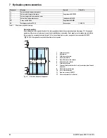
Страница 46: ...7 x Hydraulic system connection 46 FA ROTEX Solaris RPS3 P2 06 2012 Fig 7 2 Pressurised solar system with GSU Fig 7 3 Pressurised solar system with 2 Sanicube Solaris SCS 538 16 0...

Страница 47: ...ccessories 16 50 70 8 Solar circuit Optional AMK1 Mixer group Accessories 15 60 44 FLG Solaris FlowGuard regulation valve with flow indicator 16 41 02 FLS20 Flow sensor Solaris FlowSensor FLS20 flow a...

Страница 48: ...ig 7 4 Alternative solar panel arrangement TK Solaris collector temperature sensor Supplied with RPS3 P2 TR Solaris return temperature sensor TS Solaris storage tank temperature sensor TV Solaris flow...

Страница 49: ...emperature and flow sensor optional FLS 20 RDS1 pressure station Dimensions W x T x H 240 x 410 x 130 mm Operating voltage 230 V 50 Hz Solar panel circulation pump Grundfos UPS 15 65 CACAO Max electri...

Страница 50: ...1385 1423 1461 FlowSensor Sensor voltage in V according to manufacturer s specifications TV 0 50 3 50 V 0 50 0 80 1 10 1 40 1 70 2 00 2 30 2 60 2 90 3 20 3 50 Flow rate FlowSensor Measured flow in l m...

Страница 51: ...lowSensor 19 Frost protection function 32 I Installation Connection pipes 14 Storage tank extension equipment 21 Temperature sensor 18 L Language selection 36 M Malfunctions Display of events 42 Recti...

Страница 52: ...FA ROTEX Solaris RPS3 P2 06 2012 008 1610944_03 Errors and technical changes excepted Original version 008 1610949_03 06 2012 in German ROTEX...

Отзывы: