


IT
EN
10
Rossi
TX11 Operating instructions − UTD.164.06-2012.00_IT_EN
10
Rossi
Important:
values thus obtained can slightly diff er from value de-
sired. Therefore, it is advisable to verify eff ective braking torques
achieved through a dynamometric key inserted on drive end motor
shaft.
Before commissioning
, close motor with brake cover.
6.3 Electrical installation
Insulation resistance control
Before putting into service and after long stillstanding or storing pe-
riods it is necessary to measure insulation resistance between the
windings and to earth by adequate d.c. instrument (500 V).
Attention! Do not touch the terminals during and just
after the measurement because of live terminals.
Insulation resistance, measured at +25°C winding tempera-
ture, must not be lower than 10 MΩ (EN 60204) for new winding,
than 1 MΩ for winding run for a long time.
Lower values usually denote the presence of humidity in the wind-
ings; in this case let them dry (with warm air fl ow or by applying to
the windings connected in series an AC voltage not exceeding the
10% of the nominal voltage).
For use under long overloads or jamming conditions, cut-outs, mo-
tor-protections, electronic torque limiters or other similar devices
should be fi tted.
Where duty cycles involve a high number of on-load, it is advisable
to utilize
thermal probes
for motor protection (fi tted on the wiring);
magnetothermic breaker is unsuitable since its threshold must be
set higher than the motor nominal current of rating.
For no-loads starts (or with very reduced load) and whenever it is
necessary to have smooth starts, low starting currents and reduced
stresses, adopt reduced voltage starting (e.g.: star-delta starting,
starting autotransfomer, with inverter, etc.).
After making sure that the voltage corresponds to name plate data,
wire up to the electrical power supply of motor, of possible brake
and auxiliary equipments, referring to Fig. 3 and 4 and other addi-
tional indications attached to present instructions.
Select cables of suitable section in order to avoid overheating and/
or excessive voltage drops at motor terminals.
Metallic parts of motors which normally are not under volt-
age, must be fi rmly
connected to earth
through a cable of
adequate section and by using the proper terminal inside
the terminal box marked for the purpose.
In order not to alter protection class, close the terminal box by posi-
tioning correctly the gasket and by tightening all fastening screws.
For installations in environments with frequent water sprays, it is
advisable to seal the terminal box and the cable gland with adhe-
sive for seals.
For three-phase motors the direction of rotation is clockwise (drive-
end view) if connections are according to Fig. 1.
If direction of rotation is not as desired, invert two phases at the
terminals; for single-phase motors follow the instructions on Fig. 2.
In case of connection or disconnection of high polarity (
6 poles)
motor windings, there can be dangerous voltage peaks.
Pre-ar-
range the proper protection (e.g. varistors or fi lters) on the
supply line.
Also the use of inverters requires some precautions relevant to volt-
age peaks (
U
max
) and voltage gradients (d
U
/d
t
) generated by this
power supply type; the values become higher by increasing the
mains voltage
U
N
the motor size, the power supply cable length
between inverter and motor and by worsening the inverter quality.
For mains voltages
U
N
> 400 V, voltage peaks
U
MAX
> 1 000 V, volt-
age gradients d
U
/d
t
> 1 kVμs, supply cables between inverter and
motor > 30 m, it is recommended, especially in absence of proper
non-standard designs on motor (see manufacturer’s catalog), to in-
sert suitable fi lters between inverter and motor.
Indications for the installation according to «Electromagnet-
ic Compatibility (EMC)» 2004/108/EC Directive.
Asynchronous three-phase motors supplied from the line and run-
ning in continuous duty comply with EN 50081 and EN 50082
standards. No particular shieldings are necessary. This is also valid
for the motor of independent cooling fan, if any.
In case of jogging operation, any disturbance generated by inser-
tion devices must be limited through adequate wirings (as indicated
by device manufacturer).
In case of brake motor with d.c. brake (HBZ, HBV, HBVM) and recti-
fi ers RN1, RR1 ... RR8, rectifi er-brake coil group can comply with
standards EN 50081-1 (emission levels for civil environments) and
EN 50082- 2 (immunity for industrial environments) by connecting
in parallel to the rectifi er a noise-reducing capacitor or fi lter (speci-
fi cations on request; consult us).
When brake is supplied separately, brake cables must be kept sepa-
rate from power cables. It is possible to keep together brake cables
with other cables only if they are shielded.
Where motors are supplied by inverters it is necessary to follow the
wiring instructions of the manufacturer of inverter.
In case of design with encoder: install the electronic control board
as near as possible the encoder (and as far as possible from in-
verter, if any; if not possible, carefully shield the inverter); always
use twisted pairs shielded leads connected to earth on both ends;
signal cables of encoder must be separate from the power cables
(see specifi c instructions attached to the motor).
7. Connections
7.1. Motor connection
Follow schemes on Fig. 1 ... 4 to connect the motor.
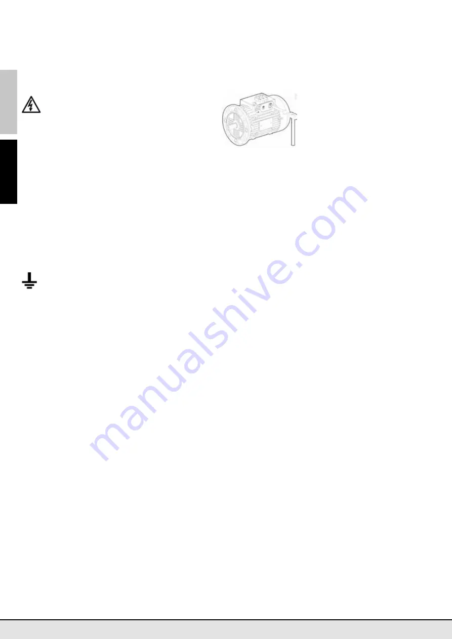
Motor
sizes
160S
: before connect-
ing the motor for the fi rst time, pro-
ceed to knockout the openings on the
terminal box to allow the cable entry;
(see fi g. on the left); after that, accu-
rately remove any fragment still re-
maining inside the terminal box; re-
store the motor protection degree
fi xing the cable glands (not provided)
with lock nut and employing the gaskets supplied inside the termi-
nal box.
Motor
sizes
160M
: use the cable glands supplied.
7.2. HBZ, HBV (HBVM) Brake (rectifi er) connection
Single-speed
motors are supplied with rectifi er already connected
to motor terminal block. Therefore, for standard duties, motor is
ready to be used without any further connections for brake supply.
For
two-speed
motors, for those
driven by inverter
and for lifting
with on-load descent braking it is necessary to supply the rectifi er
separately
with proper cables pre-arranged (for lifting it is neces-
sary to open the rectifi er supply
also on d.c. side
as shown in the
schemes). Follow the instructions of Fig. 5.
Verify that rectifi er supply voltage is the one stated on motor name
plate.
In case of brake equipped with microswitch (HBZ motor, «
,SB
», or
«
,SU
» code on name plate) refer to connection diagrams of Fig. 7.
7.3. HBF Brake connection
Motor
sizes
160S
: brake coil pre-arranged as standard for brake
supply directly from motor terminal block when motor is Y-connect-
ed (brake coil already Y-connected to the auxiliary terminal block:
re-arrange the brake coil connection in case of motor Δ-connected
or in case of separate supply with Δ voltage).
Motor
sizes
160M
: arrange on the brake auxiliary terminal block
the required brake coil connection (Δ or Y) properly positioning the
(loose) jumpers.
For both cases, before commissioning, connect the auxiliary termi-
nal block to the motor terminal block or to an external line.
For
two-speed motors
and for those driven by
inverter
it is nec-
essary to supply the brake separately with proper pre-arranged ca-
bles. Follow instructions on page 9.
Always verify that brake voltage is the one stated on motor name
plate.
7.4. Auxiliary equipment connections
Connection of independent cooling fan.
Supply wires of independent cooling fan are marked by the letter
«
V
» on cable terminals and are connected to auxiliary rectifi er ter-
minals or to another auxiliary terminal block according to schemes
of Fig. 3, in function of identifi cation code of independent cooling
fan:
– Code A: single-phase independent cooling fan (sizes 63 ... 90);
– Code D, F, M, N, P: three-phase independent cooling fan (motor
sizes 100 ... 280); usual arrangement is with Y connection with
voltages indicated below; for Δ connection, consult us.
Verify that the direction of rotation of three-phase independent cool-
ing fan is correct (air fl ow must be towards drive-end; see arrow on
fan cover); on the contrary invert two phases at the terminals.
During the installation, verify that the supply data correspond to
those of the independent cooling fan; refer to code of independent
cooling fan as per motor name plate; running of motors with inde-
pendent cooling fan is allowed only when external fan is running;
in case of running with frequent starts and stops, it is necessary to
supply the independent cooling fan continuously.
Connection of bi-metal type thermal probes, thermistor type
thermal probes (PTC), anti-condensation heater.
The connection wires are inside the terminal box and are marked by
the letter «
B
» (bi-metal type thermal probes), «
T
» (thermistor type
thermal probes PTC) or «
S
» (anti-condensation heater) on cable ter-
minals; they are connected to an auxiliary terminal block according
to schemes of Fig. 4.
Bi-metal or thermistor type thermal probes need an adequate relay
or a release device.
Anti-condensation heaters must be supplied separately from motor
and never during the operation.
The anti-condensation heater must be supplied for at least two
hours before motor commissioning, in order to achieve a full ther-
Содержание TX11 HB Series
Страница 2: ......
Страница 13: ...IT EN 13 Rossi TX11 Operating instructions UTD 164 06 2012 00_IT_EN This page is intentionally left blank...
Страница 25: ...25 Rossi Operating instructions Pagina lasciata intenzionalmente bianca This page is intentionally left blank...
Страница 26: ...26 Rossi Operating instructions Pagina lasciata intenzionalmente bianca This page is intentionally left blank...
Страница 27: ...27 Rossi Operating instructions Pagina lasciata intenzionalmente bianca This page is intentionally left blank...


