


ULTRAVIEW HARDWARE
The front panel
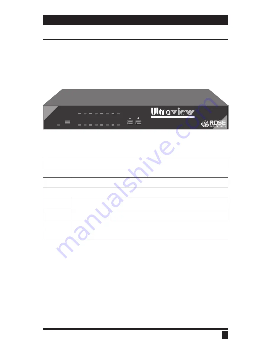
The UltraView front panel has a power switch and power LED, up to 32
LEDs, and two push-button switches. To familiarize yourself with
UltraView’s controls and indicators, review the illustration and descriptions
given below. The unit shown below is in the L style chassis but is similar for
other models.
Table 1. The front panel
POWER
Power LED: When lit indicates that unit is powered on.
ON/OFF
Power Switch: Pressing the switch turns the unit on/off, provided supplied power
adapter is properly connected.
LEDs
Indicator LEDs: Numbered pairs of LEDs indicate status of CPUs connected to corre-
sponding numbered connectors on rear panel.
SELECT (RED)
When lit shows which CPU or expansion unit you have selected for
access.
POWER
(GREEN)
When lit indicates which CPU is powered on or that expansion unit
is attached and powered on.
-/+
Computer selection switches: Changes currently selected computer from the front
panel. The - switch is used to select a numerically lower computer. The + switch is used to
select a numerically higher computer. Also used for reloading flash memory, resetting to
factory default, and diagnostics.
3
ULTRAVIEW INSTALLATION AND OPERATION MANUAL
KEYBOARD-MONITOR-MOUSE SWITCH WITH ON-SCREEN DISPLAY
ON/OFF
1
2
3
4
5
6
7
8
POWER
SELECT
SELECT
SELECT
SELECT
SELECT
SELECT
SELECT
SELECT
POWER
POWER
POWER
POWER
POWER
POWER
POWER
POWER
Figure 1. The UltraView front panel
Содержание UltraView
Страница 2: ......
Страница 50: ......
Страница 51: ......
Страница 52: ...ELECTRONICS 10707 STANCLIFF ROAD n HOUSTON TEXAS 77099 n TEL 281 933 7673 ...


