background image

27

Video Composition Operations

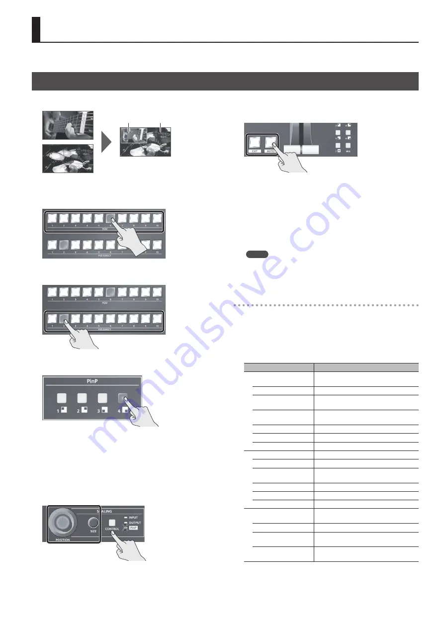
This composites video. The V-800HD MK II has four built-in types of composition.

Compositing Using Picture-in-Picture (PinP)

This composites video in an inset screen onto a different background video. This section describes operations when in the PGM/PST mode (p. 22).

Background video

Inset screen

1. 

Press a cross-point button in the PGM section to select the 

video you want to make the background video.

2. 

Press a cross-point button in the PST/EFFECT section to 

select the video you want to make the inset screen.

3. 

Press one of the PinP [1] to [4] buttons to turn on video 

composition (lighted).

The selected button lights up in green, and a preview of the 

composition results is displayed in the PVW section of the multi-view 

monitor.
At this stage, the final output has not yet been changed.

4. 

Use the [POSITION] joystick and the [SIZE] knob to adjust 

the position and size of the inset screen.

Press the [CONTROL] button several times to make the PinP indicator 

light up. The enables you to manipulate the inset screen.

5. 

Press the [AUTO] or [CUT] button.

At this time, the PinP button and the cross-point button in the PST/

EFFECT section light up in red.
Pressing the [AUTO] or [CUT] button a second time makes the inset 

screen disappear.
*  You can also display or hide the inset screen by operating the video 

fader.

6. 

To turn off video compositing, press the PinP button a 

second time.

MEMO

The video transition-time setting is applied as the fade time when 

you use the [AUTO] button to display or hide the inset screen.

Making Detailed Settings for the Inset Screen

You can make separate sets of settings for inset-screen position and 

size, the border around the inset screen, and other values for each 

PinP button.
Select the [MENU] button 

g

 “PinP” 

g

 choose one of the selections 

from “Position 1” through “Position 4” 

g

 press the [ENTER] button, 

then make the settings for the following menu items.

Menu item

Explanation

PinP

Use the following items to make the settings 

for the inset screen.

Size

This adjusts the zoom ratio.

Position H

This adjusts the display position in the 

horizontal direction.

Position V

This adjusts the display position in the vertical 

direction.

Cropping Type

This sets the cropping type.

Manual Cropping H

This sets the horizontal cropping width. (*1)

Manual Cropping V

This sets the vertical cropping width. (*1)

Border

Use the following items to adjust the border.

Width

This adjusts the border width.

Color

Use the following items to adjust the color of 

the border.

Red

This adjusts the red level.

Green

This adjusts the green level.

Blue

This adjusts the blue level.

View

Use the following items to adjust the video 

displayed in the inset screen.

Size

This adjusts the zoom ratio.

Position H

This adjusts the display position in the 

horizontal direction.

Position V

This adjusts the display position in the vertical 

direction.

(*1) This is available when “Cropping Type” is set to “Manual.”

Содержание V-800HD MK II

Страница 1: ...stem Information Copyright 2017 ROLAND CORPORATION Owner s Manual this document Read this first It explains the basic things you need to know in order to use the V 800HD MK II PDF Manual download from theWeb 5 5 Reference Manual This manual covers all menu items of the V 800HD MK II It also describes control via MIDI and RS 232 To obtain the PDF manual 1 Enter the following URL in your computer ht...

Страница 2: ...ovided plug does not fit into your outlet consult an electrician for replacement of the obsolete outlet WARNING IMPORTANT As the colours of the wires in the mains lead of this apparatus may not correspond with the coloured markings identifying the terminals in your plug proceed as follows The wire which is coloured GREEN AND YELLOW must be connected to the terminal in the plug which is marked by t...

Страница 3: ...ons 22 Switching the Video 22 About the Operation Mode for Video Transitions 22 Switching Using the PGM PST Mode 22 Switching in the A B Mode 23 Using Imported Still Images 24 Importing a Still Image from a USB Flash Drive 24 Capturing a Still Image from Final output Video 24 Assigning a Still Image to Channel 9 or 10 25 Deleting a Still Image 25 Applying a Fade to the Final Output Video Output Fa...

Страница 4: ... foreign objects e g flammable objects coins wires or liquids e g water or juice to enter this product Doing so may cause short circuits faulty operation or other malfunctions WARNING Turn off the unit if an abnormality or malfunction occurs Immediately turn the unit off remove the power cord from the outlet and request servicing by your retailer the nearest Roland Service Center or an authorized ...

Страница 5: ...a power plug if your hands are wet Otherwise you could receive an electric shock Disconnect all cords cables before moving the unit Before moving the unit disconnect the power plug from the outlet and pull out all cords from external devices Before cleaning the unit disconnect the power plug from the outlet If the power plug is not removed from the outlet you risk receiving an electric shock Whene...

Страница 6: ... liability concerning the restoration of any stored content that has been lost Additional Precautions Any data stored within the unit can be lost as the result of equipment failure incorrect operation etc To protect yourself against the irretrievable loss of data try to make a habit of creating regular backups of the data you ve stored in the unit Roland assumes no liability concerning the restora...

Страница 7: ...for connectors and cables leave 2U of clearance above the unit Before mounting turn off the power to the V 800HD MK II and detach the power cord and all connection cables Use all threaded holes at 4 locations on each side for a total of 8 to secure the unit to the rack using screws Screws for rack mounting are not included When mounting the unit use due caution to ensure that your fingers do not g...

Страница 8: ...wn below displaying the item to work with INPUT g OUTPUT g PinP g Dark Input video Final output video Inset screen 4 AUX 1 10 buttons These show the input status of signals sent to the AUX bus input channels 1 10 and input to cross points Lighted in red A signal input channel 1 10 is being sent to the AUX bus You can use the AUX 1 10 buttons to change the signal sent to the AUX bus Lighted in gree...

Страница 9: ... the amount of keying transparency p 28 KEY GAIN knob During key compositing this adjusts the degree of edge blur the semi transmissive region for keying KEY ON button This switches key composition on or off When on the KEY ON button lights up The color of the lighted button indicates the output destination of the compositing results Lighted in green Preview output displayed in the PVW section of ...

Страница 10: ...per connectors matching those of the other devices you are using AC IN connector This is for connecting the included power cord Be sure to use the included power cord for connecting the power supply POWER switch This turns the power on and off p 13 TALLY 1 2 connectors Here you connect devices provided with a tally light feature p 34 RS 232 connector Here you connect a remote control device such a...

Страница 11: ... assigned to each input channel p 16 When inputting video to a DVI I HDMI IN connector you must use the SIGNAL switch next to the connector to select DVI A analog or DVI D digital MIDI OUT THRU IN connectors Here you connect a remote control MIDI device for operating the V 800HD MK II remotely p 34 SD OUT connector RGB COMPONENT OUT connector DVI D HDMI OUT connectors SDI OUT connector This output...

Страница 12: ...ssignments at the cross point p 33 also changes the order of displayed sources Still images imported into the V 800HD MK II p 24 are assigned to channel 9 or 10 and so they are not displayed MEMO You can change the label names displayed on the multi view monitor Use the MENU button g System g Multi view Label to select PGM PVW or Ch 1 to Ch 8 then change the label name Also using Multi view Label ...

Страница 13: ...ake settings for video and for the V 800HD MK II itself Menus are shown only on the multi view monitor connected to the HDMI OUT connector p 12 1 Press the MENU button to display the menu The MENU button lights up the menu categories are displayed 2 Press the CURSOR buttons to select a category then press the ENTER button to confirm the selection The menu items for the selected category are displa...

Страница 14: ...00 60 Hz COMPOSITE IN 480 59 94i 576 50i The refresh rates are the maximum value for each resolution The input format is detected automatically Output Formats Output connector Frame rate When set at 59 94 Hz When set at 50 Hz SDI OUT 480 59 94i 576 50i 720 59 94p 720 50p 1080 59 94i 1080 50i 1080 59 94p 1080 50p RGB COMPONENT OUT component signal 1 480 59 94p 576 50p 720 59 94p 720 50p 1080 59 94p...

Страница 15: ...ponent RGB COMPONENT OUT connector Value Video signal that is output 480 576p4 3 2 Component 480 576p16 9 2 720p 1080p VGA SVGA XGA RGB WXGA SXGA FWXGA SXGA UXGA WUXGA 2 At 480 576p for the aspect ratio select either 4 3 or 16 9 Composite SD OUT connector Value Explanation 480 576i4 3 The output format is fixed at 480 576i and cannot be changed For the aspect ratio select either 4 3 or 16 9 480 57...

Страница 16: ...alue DVI D DVI D HDMI DVI A DVI A RGB Component This inputs video via an RGB COMPONENT IN connector Shared Input This shares the video source on the previous channel among channels 5 through 8 For details refer to the Sharing a Video Source column on this page Shared Input can be set for channels 6 8 Ch 9 Value Explanation Still Image This assigns a still image p 24 Ch 10 Value Explanation Still I...

Страница 17: ...ut Fade Selector DSK Mixer Video Mixer PinP Key Still Image Still Image Background 1 2 3 4 5 6 7 8 9 10 5 5 5 5 5 5 5 5 5 5 Frame Synchronizer Scaller Color Correct Color Correct 2 4 Cross point PVW PGM AUX AUX Source 3 Press the MENU button to quit the menu Assigning a Bus to an Output Connector 1 Select the MENU button g Output g Source Assign to select the output connector whose bus assignment ...

Страница 18: ...e This sets the color space 1 This is available when Type is set to Manual RGB Component RGB COMPONENT OUT connector Menu item Explanation Color Space This sets the color space Scaling You use the following items to make settings for scaling Zoom This adjusts the zoom ratio Type This sets the scaling type Manual Size H This adjusts the horizontal size 2 Manual Size V This adjusts the vertical size...

Страница 19: ... turns on off the flicker filter Scaling This sets the scaling The menu items are similar for channels 1 4 Color Correction This performs color correction The menu items are similar for channels 1 4 Sampling You use the following items for make settings for sampling Auto Sampling Pressing the ENTER button executes automatic settings for sampling Position H This adjusts the horizontal start positio...

Страница 20: ...ity of source equipment You can use the MENU button g Output g the Output menu to check the status of HDCP compatibility of output destination equipment HDCP is displayed on screen according to the status of HDCP support Menu HDCP support status Input Copyright protected HDCP video is being input Output An HDCP compatible device is connected Output from Connectors When HDCP is set to ON video is o...

Страница 21: ...chronized to the VSYNC signal input via SDI 5 5 When Set to External or Input SDI 1 4 Adjust the following System menu items as needed MENU item Explanation Clock Adjust This adjusts the phase horizontally Adjust this when output is horizontally out of sync with the operation of other devices using the same clock Line Adjust This adjusts the phase vertically Adjust this when output is vertically o...

Страница 22: ... EFFECT section to select and check the preset video the video to output next then switch it 1 Move the video fader all the way to one end or the other 2 Press one of the WIPE PATTERN 1 through 7 buttons or the MIX button to select the transition effect The selected button lights up WIPE PATTERN 1 7 buttons In this transition the original video is broken into by the next video You can change the w...

Страница 23: ... video You can change the wipe pattern and wipe direction Select the MENU button g Transition g choose one of the selections from Wipe Patter 1 through Wipe Patter 7 g make settings for Pattern and Direction MIX button The two pictures are blended together as the video is switched 4 Move the video fader in the direction opposite to the direction in step 1 The output video is switched MEMO Directly...

Страница 24: ... Still Image Memory No then use the VALUE knob to select a memory number 1 through 16 for saving the still image A symbol is displayed for memory numbers where a still image is already saved 5 Select Load then press the ENTER button The Load File Select screen appears The names of the files on the USB flash drive are displayed on this screen 6 Select the still image file you want to import then pr...

Страница 25: ...mory numbers where a still image is already saved Position H This adjusts the horizontal display position of the still image Position V This adjusts the vertical display position of the still image Color Correction You use the following items to perform color correction for the still image Brightness This adjusts the brightness Contrast This adjusts the contrast Saturation This adjusts the saturat...

Страница 26: ...ory numbers where a still image is already saved Position H This adjusts the horizontal display position of the still image Position V This adjusts the vertical display position of the still image Color Correction You use the following items to perform color correction for the still image Brightness This adjusts the brightness Contrast This adjusts the contrast Saturation This adjusts the saturati...

Страница 27: ...positing press the PinP button a second time MEMO The video transition time setting is applied as the fade time when you use the AUTO button to display or hide the inset screen Making Detailed Settings for the Inset Screen You can make separate sets of settings for inset screen position and size the border around the inset screen and other values for each PinP button Select the MENU button g PinP ...

Страница 28: ...ess threshold to make white transparent Luminance 2 Black This uses a brightness threshold to make black transparent Chroma 1 Blue This uses a color threshold to make blue transparent Chroma 2 Green This uses a color threshold to make green transparent 3 Press the MENU button to quit the menu Compositing Using Key 1 Press a cross point button in the PST EFFECT section to select the video you want ...

Страница 29: ...e or Chroma 2 Green you can use the Key menu to fine tune the key color Menu item Explanation Hue You use the following items to adjust the hue of the key color Fine This adjusts the center position for hue Width This adjusts the hue width range Saturation This adjusts the saturation of the key color Compositing Using an External Key You can perform key composition that uses an external key Fill c...

Страница 30: ...use the DSK menu to fine tune the key color Menu item Explanation Hue You use the following items to adjust the hue of the key color Fine This adjusts the center position for hue Width This adjusts the hue width range Saturation This adjusts the saturation of the key color Compositing Using DSK 1 Input the logo or image By factory default the settings are such that text and image input on channel ...

Страница 31: ...to save the settings The bank changes While the BANK button is lighted the button for the currently selected bank number lights up 3 Press the MEMORY button for the number whose setting you want to save The current settings are saved MEMO The state of the OUTPUT FADE button on the operation panel is not saved in memory The following settings are also not saved in memory Only a single set is saved ...

Страница 32: ...Parameter screen is displayed 2 Select Save then press the ENTER button The Save File Select screen is displayed 3 Select the file to overwrite then press the ENTER button 4 When the message Push ENTER to execute appears press the ENTER button If you want to cancel the operation press the EXIT button The file is saved by overwriting 5 Press the MENU button to quit the menu Recalling This recalls t...

Страница 33: ...sh ENTER to execute appears press the ENTER button If you want to cancel the operation press the EXIT button Formatting of the USB flash drive is carried out 3 Press the MENU button to quit the menu Changing Cross point Assignments You can change the channels assigned to the cross point 1 through 10 buttons You can also disable operation of a cross point button by assigning no channel to the butto...

Страница 34: ...hat visual expression could be linked with musical performance Video equipment that is compatible with MIDI Visual Control can be connected to electronic musical instruments via MIDI in order to control video equipment in tandem with a performance Outputting aTally Signal This outputs a tally signal from the TALLY 1 or 2 connector Specification of theTALLY Connector 5 4 3 2 1 15 14 13 12 11 10 9 8...

Страница 35: ...ow This enables you to use the AUX 1 through 10 buttons to directly select the input channel to send 1 At the key menu set Mode to Self Key 2 At the Output menu set AUX Source to any one of the Input Ch 1 10 settings No still image can be assigned to an output fade Is the still image assigned to channel 10 A still image cannot be assigned to channel 10 and output fade at the same time When assigni...

Страница 36: ...I A DVI I HDMI RGB COMPONENT Input Select Signal Select PGM PST EFFECT DSK Source Input Ch 1 Input Ch 10 Key Mode Self Key External Key FRAMESYNCHRONIZER SCALER COLOR CORRECTOR COLOR CORRECTOR DVI I HDMI RGB COMPONENT DVI I HDMI RGB COMPONENT REFERENCE IN STILL IMAGE STILL IMAGE BACKGROUND COMPOSITE SDI DVI D DVI A DVI D DVI A DVI D DVI A Shared Input Input Select REFERENCE THRU VIDEO MIXER PinP K...

Страница 37: ...PVW AUX AUX Source Fade to Background Mixer Input Mixer Output DSK Source DSK Output Still Image to Still Image Mmeory Output Freeze Fade to Still Image Mode DSK RGB COMPONENT COMPOSITE Source Bus Output Capture MULTI VIEW OUTPUT HDMI MULTI VIEW OUTPUT FADE SCALER COLOR CORRECTOR SCALER COLOR CORRECTOR COLOR CORRECTOR SELECTOR Cannot be used at the same time ...

Страница 38: ...deo HD Select DVI D HDMI or Analog RGB using menu per channel Output Connectors 3G HD SD SDI BNC type x 2 Conforms to SMPTE 424M Level A Level B 292M 259M C DVI D HDMI DVI I type x 2 HDMI x 1 for multi view monitor Analog Video HD Component Mini D sub 15 pin type x 1 Combined use with Analog RGB Analog Video SD Composite BNC type x 1 Combined use with Analog Video HD Does not synchronize with Refe...

Страница 39: ...is subject to the following two conditions 1 this device may not cause harmful interference and 2 this device must accept any interference received including interference that may cause undesired operation To assure continued FCC emission limit compliance use only shielded interface cables when connecting to other device Any unauthorized changes or modifications not expressly approved by the party...

Страница 40: ... 5 1 0 0 0 5 6 3 0 2 0 2 For EU Countries ...

Отзывы: