Roland Color CAMM PC-50 Скачать руководство пользователя страница 8

6

5 Basic Operation

5-1  DIP Switch Settings

DIP switches settings must be made only
when the power is turned off.

NOTICE

5-2  Powering On

When the power switch is pressed to power on the unit, the
tool carriage moves.  Use caution to ensure that your hands or
other objects do not become caught in the moving parts.

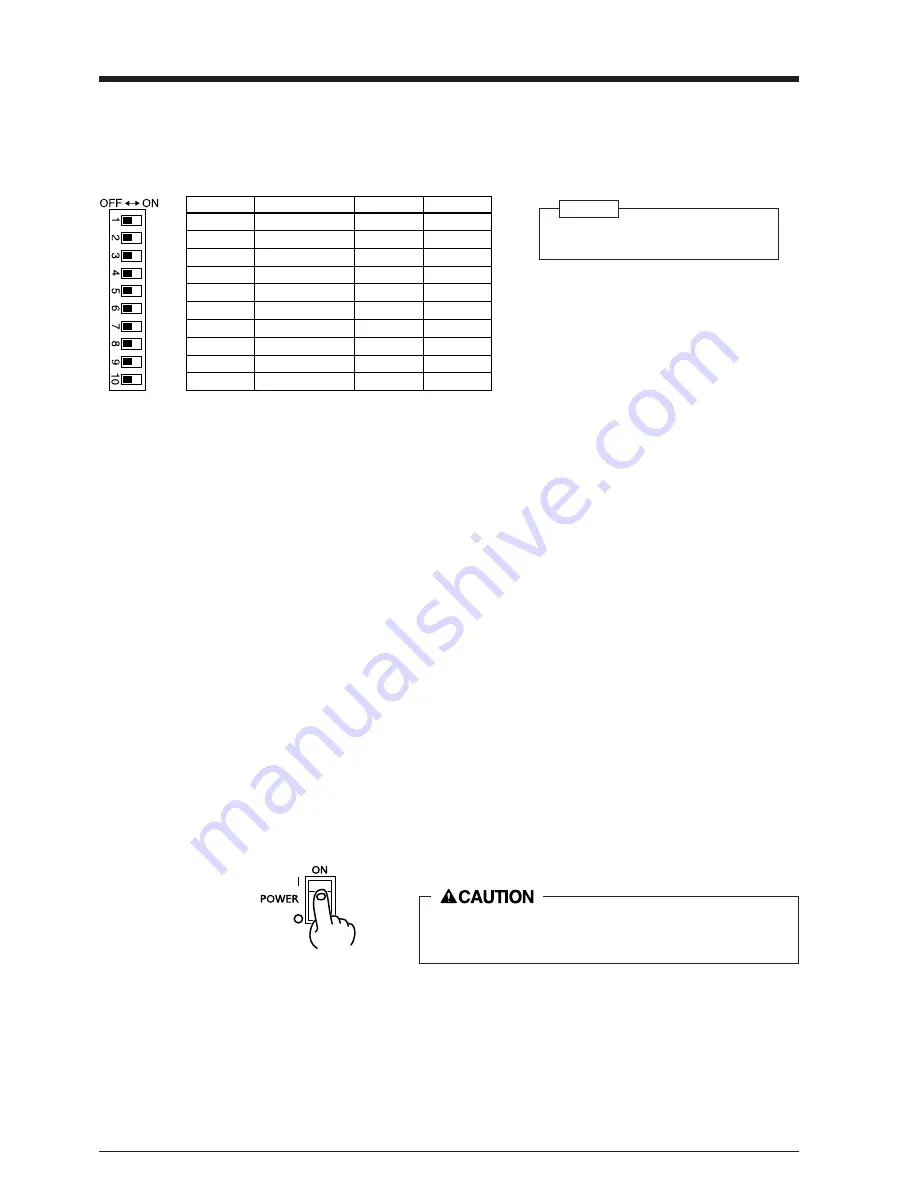
Press the side of the
switch marked “ | ”.

All DIP switches are set to OFF when shipped from the factory.
The DIP switches are located on the right face of the unit, near the bottom.

SW-1–4 : Sets the communication parameters for a serial connection. When the PC-50 is connected to the computer through the serial

port, be sure that the communication parameters for SW-1 to SW-4 are set correctly, matching the computer port settings.

  (Data length is fixed to 8 bits.  It is automatically determined whether the number of stop bits is 1 or 2.)

SW-5

: Detects automatically the front edge of loaded material.  To detect the front edge of loaded material, set SW-5 to ON (en-

abled).

SW-6

: Detects length of cut material automatically.  Switch to ON (enabled) when loading sheet material, and OFF (disabled) when

loading roll material.

SW-7

: Sets the amount of offset for the cutter blade.  Set to OFF when using a tool with a blade offset of 0.25 mm, or to ON when

using a tool with a blade offset of 0.5 mm.

SW-8

: Sets the weight of the material. SW-8, which controls the material weight, should normally be set to OFF (light).  Cutting

speed slows down when switch is turned ON, but the force used to move the material and the blade increases.

SW-9

: Acclimates the machine and the material before cutting or printing, which can produce more attractive printing or cutting

results.  This is normally set to OFF (enabled).

 (When the cut-sheet mode (SW-6) is set to ON (enabled), the prefeed mode is disabled, regardless of the setting of SW-9.)

*This option should be selected only when you are using

optional blade, ZEC-U3050.
Please contact your dealer for more information.

DIP switch

Function

OFF

ON

SW-1

Baud rate

9600

19200

SW-2

Parity

Disable

Enable

SW-3

Parity

ODD

EVEN

SW-4

Handshake

Hardwire

XON/XOFF

SW-5

Front edge sense

Disable

Enable

SW-6

Cut sheet mode

Disable

Enable

SW-7

Blade offset

0.25

0.5*

SW-8

Long output mode

Light

Heavy

SW-9

Prefeed mode

Enable

Disable

SW-10

(Not Used)

5  Basic Operation

Содержание Color CAMM PC-50

Страница 1: ...USER S MANUAL PC 50...

Страница 2: ...device pursuant to Part 15 of the FCC Rules These limits are designed to provide reasonable protection against harmful interference when the equipment is operated in a commercial environment This equi...

Страница 3: ...Names and Functions 3 2 1 Front View 3 2 2 Rear View 3 2 3 Operation Panel 4 3 Set up and Connections 5 4 What the PC 50 Can Do 5 5 Basic Operation 6 5 1 DIP Switch Settings 6 5 2 Powering On 6 5 3 In...

Страница 4: ...sure the safety of the area around the platen before switching on the power Do not install in an unstable or high location Do not install the machine on the edge of a table or it may fall Handle the b...

Страница 5: ...terial to correctly track it through the machine Cutting Carriage The blade holder is mounted here Pinch Roller Right This presses the material against the grit roller Printing Carriage The ribbon car...

Страница 6: ...pressed in order to begin printing or cutting Cursor Keys Pressing the and keys causes the tool or material to move in the specified direction PAUSE LED Lights when the PAUSE key is pressed to stop th...

Страница 7: ...16 in height Since the material moves during printing and cutting make sure the unit is placed on a stable sturdy surface Also make sure there is nothing that can block the material at both front and...

Страница 8: ...ON enabled when loading sheet material and OFF disabled when loading roll material SW 7 Sets the amount of offset for the cutter blade Set to OFF when using a tool with a blade offset of 0 25 mm or to...

Страница 9: ...il the collar is flush with the carriage Tool securing screw 1 Loosen 3 Tighten Cutting carriage Adjusting the Cutter Blade Blade adjustment may be necessary when cutting material whose carrier paper...

Страница 10: ...head 5 Basic Operation If the ink ribbon runs out while printing 1 If the ink ribbon runs out during printing operation stops The PAUSE LED and CHANGE LED will blink simultaneously 2 Remove the old r...

Страница 11: ...ifies MAGENTA and stops The CHANGE LED blink The CHANGE LED blink If any of the four colors C M Y or K is not used the PC 50 does not stop at that color Special color Printing This is used to add emph...

Страница 12: ...SETUP LED lights up Lower the sheet loading levers to secure the material in place 1 Load roll material on the sheet base included with the PC 50 Roller base Rear Front 2 Gently press the roll materi...

Страница 13: ...the computer 2 Press the SETUP key 1 2 Press the PAUSE key To resume printing or cutting Press the PAUSE key To Terminate printing or cutting The carriages moves to the left edge of the printing cutti...

Страница 14: ...o the position on the material where the cutting test is to be executed Cutting test starts 1 First peel off the round section shaded as shown When it can be peeled by itself without disturbing the sq...

Страница 15: ...hen the unit is not in use keep the pinch rollers raised The pinch rollers may be deformed if left engaged If you do not intend to use the unit for an extended period of time disconnect the unit from...

Страница 16: ...al from the roll and pass it through the unit Material alignment stickers 25 mm 1 or more Use material that is wider by 50 mm 2 or more than the width of the printing or cutting to be performed Pull o...

Страница 17: ...D light up This pattern indicates the current line pitch Use the table at right as a reference to press the and keys and make the desired line pitch setting After making the setting press the SETUP ke...

Страница 18: ...s will extend the life of the blade Excessive cutter forces can cause the blade to wear out quickly Care should be taken 8 About the Printing Cutting Area Factory default When DIP switch SW 6 cut shee...

Страница 19: ...leaning sheet REMOVE the blade holder Press the CLEANING key 1 3 2 Head cleaning is finished when the carriage stops moving Pressing the CLEANING key has no effect if an ink cartridge is installed Rem...

Страница 20: ...lint free cloth before use LOAD the cleaning sheet Matt face is up side Lower the sheet loading levers to secure the material in place 4 REMOVE the blade holder 2 the ink ribbon cartridge TAKE OUT 1...

Страница 21: ...DIP switches correctly see 5 1 DIP Switch Settings PC 50 Is the computer set up correctly Check the following items DIP switches Memory switches Interface board Communication parameters Other settings...

Страница 22: ...s seen in areas where there is no printing When this occurs use alcohol to wipe away soiling on the sheet immediately after printing Is there faint soiling around printed areas Clean the printing head...

Страница 23: ...ut an alignment test by using the key to advance the material by the amount that will be used for printing or cutting Make sure that the material travels correctly through the machine If roll material...

Страница 24: ...ET CHANGE CLEANING TEST LED POWER ERROR SETUP PAUSE BASE POINT SET CHANGE BUSY Power consumption 1 0 A 110 V 1 0 A 117 V 0 5 A 220 V 0 5 A 230 V 0 5 A 240 V Acoustic noise level Printing Cutting mode...

Страница 25: ...R4 971015...

Отзывы: