Roland Color CAMM PC-50 Скачать руководство пользователя страница 15

13

5  Basic Operation

5-10  Performing a Self-test

The PC-50 is equipped with a “self-test” function to allow you to check whether or not it is capable of operating normally. If the PC-50 is
not performing correctly, follow the steps below to perform a self-test.
A computer is not required in order to carry out the self-test.
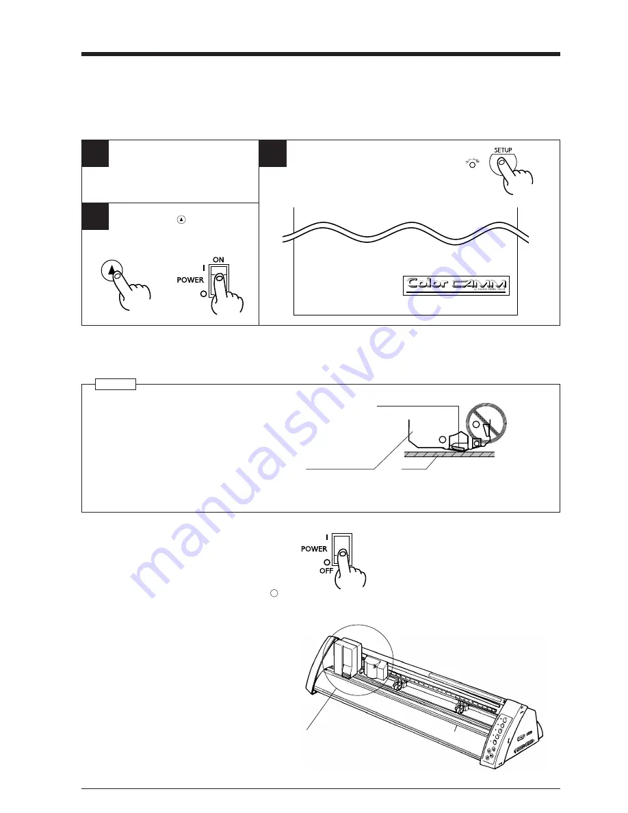
5-11  Powering Off

NOTICE

• Do not switch off the power while the printing head is lowered.

Doing so may damage the head and impair printing performance.

Platen

Ribbon cartridge

Printing head is lowered

• When the unit is not in use, keep the pinch rollers raised. The pinch rollers may be deformed if left engaged.
• If you do not intend to use the unit for an extended period of time, disconnect the unit from the power outlet.

Press the side of
the switch marked
with “ 

 ”.

Carriage position when
switching off the power

When the SETUP key is pressed to release
the setup state, the carriage moves to the
position shown in the figure, then stops.
Switch off the power when the carriage is at
this position.

1

3

2

Hold down the 

 key on the panel

while you turn the power on.

+

Operations is normal if the figure shown at below.

Install a blade and ribbon cartridge
in the PC-50.
Performing a cutting test.

Load the material, and press the SETUP key.

Содержание Color CAMM PC-50

Страница 1: ...USER S MANUAL PC 50...

Страница 2: ...device pursuant to Part 15 of the FCC Rules These limits are designed to provide reasonable protection against harmful interference when the equipment is operated in a commercial environment This equi...

Страница 3: ...Names and Functions 3 2 1 Front View 3 2 2 Rear View 3 2 3 Operation Panel 4 3 Set up and Connections 5 4 What the PC 50 Can Do 5 5 Basic Operation 6 5 1 DIP Switch Settings 6 5 2 Powering On 6 5 3 In...

Страница 4: ...sure the safety of the area around the platen before switching on the power Do not install in an unstable or high location Do not install the machine on the edge of a table or it may fall Handle the b...

Страница 5: ...terial to correctly track it through the machine Cutting Carriage The blade holder is mounted here Pinch Roller Right This presses the material against the grit roller Printing Carriage The ribbon car...

Страница 6: ...pressed in order to begin printing or cutting Cursor Keys Pressing the and keys causes the tool or material to move in the specified direction PAUSE LED Lights when the PAUSE key is pressed to stop th...

Страница 7: ...16 in height Since the material moves during printing and cutting make sure the unit is placed on a stable sturdy surface Also make sure there is nothing that can block the material at both front and...

Страница 8: ...ON enabled when loading sheet material and OFF disabled when loading roll material SW 7 Sets the amount of offset for the cutter blade Set to OFF when using a tool with a blade offset of 0 25 mm or to...

Страница 9: ...il the collar is flush with the carriage Tool securing screw 1 Loosen 3 Tighten Cutting carriage Adjusting the Cutter Blade Blade adjustment may be necessary when cutting material whose carrier paper...

Страница 10: ...head 5 Basic Operation If the ink ribbon runs out while printing 1 If the ink ribbon runs out during printing operation stops The PAUSE LED and CHANGE LED will blink simultaneously 2 Remove the old r...

Страница 11: ...ifies MAGENTA and stops The CHANGE LED blink The CHANGE LED blink If any of the four colors C M Y or K is not used the PC 50 does not stop at that color Special color Printing This is used to add emph...

Страница 12: ...SETUP LED lights up Lower the sheet loading levers to secure the material in place 1 Load roll material on the sheet base included with the PC 50 Roller base Rear Front 2 Gently press the roll materi...

Страница 13: ...the computer 2 Press the SETUP key 1 2 Press the PAUSE key To resume printing or cutting Press the PAUSE key To Terminate printing or cutting The carriages moves to the left edge of the printing cutti...

Страница 14: ...o the position on the material where the cutting test is to be executed Cutting test starts 1 First peel off the round section shaded as shown When it can be peeled by itself without disturbing the sq...

Страница 15: ...hen the unit is not in use keep the pinch rollers raised The pinch rollers may be deformed if left engaged If you do not intend to use the unit for an extended period of time disconnect the unit from...

Страница 16: ...al from the roll and pass it through the unit Material alignment stickers 25 mm 1 or more Use material that is wider by 50 mm 2 or more than the width of the printing or cutting to be performed Pull o...

Страница 17: ...D light up This pattern indicates the current line pitch Use the table at right as a reference to press the and keys and make the desired line pitch setting After making the setting press the SETUP ke...

Страница 18: ...s will extend the life of the blade Excessive cutter forces can cause the blade to wear out quickly Care should be taken 8 About the Printing Cutting Area Factory default When DIP switch SW 6 cut shee...

Страница 19: ...leaning sheet REMOVE the blade holder Press the CLEANING key 1 3 2 Head cleaning is finished when the carriage stops moving Pressing the CLEANING key has no effect if an ink cartridge is installed Rem...

Страница 20: ...lint free cloth before use LOAD the cleaning sheet Matt face is up side Lower the sheet loading levers to secure the material in place 4 REMOVE the blade holder 2 the ink ribbon cartridge TAKE OUT 1...

Страница 21: ...DIP switches correctly see 5 1 DIP Switch Settings PC 50 Is the computer set up correctly Check the following items DIP switches Memory switches Interface board Communication parameters Other settings...

Страница 22: ...s seen in areas where there is no printing When this occurs use alcohol to wipe away soiling on the sheet immediately after printing Is there faint soiling around printed areas Clean the printing head...

Страница 23: ...ut an alignment test by using the key to advance the material by the amount that will be used for printing or cutting Make sure that the material travels correctly through the machine If roll material...

Страница 24: ...ET CHANGE CLEANING TEST LED POWER ERROR SETUP PAUSE BASE POINT SET CHANGE BUSY Power consumption 1 0 A 110 V 1 0 A 117 V 0 5 A 220 V 0 5 A 230 V 0 5 A 240 V Acoustic noise level Printing Cutting mode...

Страница 25: ...R4 971015...

Отзывы: