9
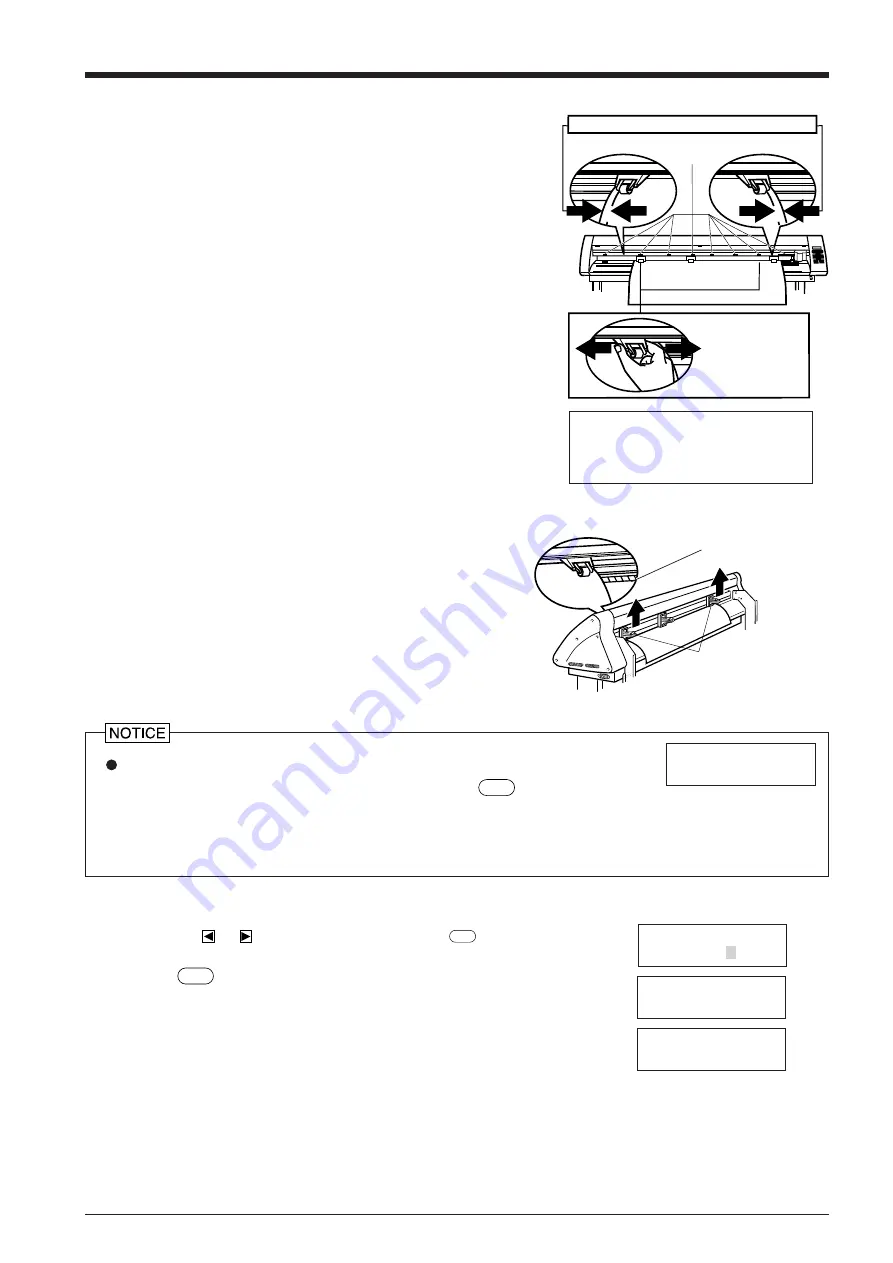
(2) Move the left and right pinch rollers so that they are close to the
respective left and right edges of the material. When using a material
that is wider than 762 mm (30") , move the middle pinch roller to a
position near the center of the left and right pinch rollers. (The PNC-
1210 has no middle pinch roller.) When doing this, make sure that
the grit rollers are under the pinch rollers.
Seals showing the positions of the grit rollers are affixed to the areas
where the carriage moves. You can use these stickers to confirm the
locations of the grit rollers when the grit rollers are hidden by the
material.
If the pinch rollers are difficult to move, try moving the sheet loading
lever on the back of the unit at the same time.
Move the pinch
rollers to inside
the edges of the
sheet
Stickers showing the locations of the
grit rollers
Make sure the left and right margins are the same size
(3) Align the right edge of the material with the two guide lines located in
front of and behind the grit roller on the control panel side, and load
the material so that it is completely straight.
Lift the sheet loading lever on the back of the unit to lower the pinch
roller and clamp the material.
Be sure to move the pinch rollers above the grit rollers when securing a material in the unit.
Moving the pinch roller to the area of the grit roller and pressing the
SETUP
key causes the message
at right to appear.. If this occurs, raise the sheet loading levers and move the pinch rollers to the
proper positions above the grit rollers.
Reposition the material to match this new alignment, then lower the sheet loading levers to hold the material in place.
Change Pinch
Roller Position
(4) When you close the front cover, the message shown at right appears on the control
panel. Press
or
to display “PIECE,” then press the
ENTER
key.
(5) Press the
SETUP
key. The tool carriage will move from side to side and the material will
move forward and backward to detect the size of the material. After this sensing is
finished, the front edge of the material is aligned with the cutting starting position.
(6) If material offset or alignment problems become apparent while the 1860/1410/1210 is
scanning the piece in step (5) above, the material has not been loaded straight. Be sure to
load the material straight. Set the movable left and right pinch rollers inside the material
edges.
Close the front cover
SELECT SHEET
ROLL EDGE PIECE
WIDTH LENGTH
28920 150
PRESS SETUP KEY
When using a material which is narrower than 762 mm (30") , do not
lower the pinch rollers.
Guide line
Before attempting to move the pinch
roller, be sure to lower the sheet
loading lever to raise the pinch roller.
Lift the sheet
loading levers
Material
Содержание Camm-1 Pro GX-640
Страница 8: ...v MEMO...
Страница 38: ...30 Automatic backspace 13 CHARACTER SET...
Страница 41: ...R9 980506...


