


12-bit Analog-to-Digital Converter (S08ADCV1)
MC9S08QE128 MCU Series Reference Manual, Rev. 2
Freescale Semiconductor
193
digital value of the analog signal. The result of the conversion is transferred to ADCRH and ADCRL upon
completion of the conversion algorithm.
If the bus frequency is less than the f
ADCK
frequency, precise sample time for continuous conversions
cannot be guaranteed when short sample is enabled (ADLSMP=0). If the bus frequency is less than 1/11th
of the f
ADCK
frequency, precise sample time for continuous conversions cannot be guaranteed when long
sample is enabled (ADLSMP=1).
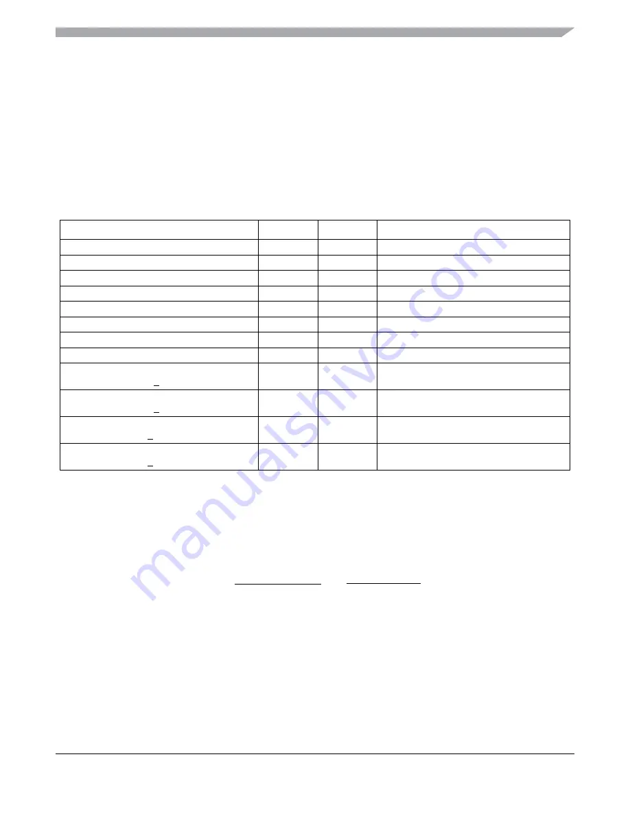
The maximum total conversion time for different conditions is summarized in
.
The maximum total conversion time is determined by the clock source chosen and the divide ratio selected.
The clock source is selectable by the ADICLK bits, and the divide ratio is specified by the ADIV bits. For
example, in 10-bit mode, with the bus clock selected as the input clock source, the input clock divide-by-1
ratio selected, and a bus frequency of 8 MHz, then the conversion time for a single conversion is:
NOTE
The ADCK frequency must be between f
ADCK
minimum and f
ADCK
maximum to meet ADC specifications.
Table 10-12. Total Conversion Time vs. Control Conditions
Conversion Type
ADICLK
ADLSMP
Max Total Conversion Time
Single or first continuous 8-bit
0x, 10
0
20 ADCK 5 bus clock cycles
Single or first continuous 10-bit or 12-bit
0x, 10
0
23 ADCK 5 bus clock cycles
Single or first continuous 8-bit
0x, 10
1
40 ADCK 5 bus clock cycles
Single or first continuous 10-bit or 12-bit
0x, 10
1
43 ADCK 5 bus clock cycles
Single or first continuous 8-bit
11
0
5
μ
s + 20 ADCK + 5 bus clock cycles
Single or first continuous 10-bit or 12-bit
11
0
5
μ
s + 23 ADCK + 5 bus clock cycles
Single or first continuous 8-bit
11
1
5
μ
s + 40 ADCK + 5 bus clock cycles
Single or first continuous 10-bit or 12-bit
11
1
5
μ
s + 43 ADCK + 5 bus clock cycles
Subsequent continuous 8-bit;
f
BUS
>
f
ADCK
xx
0
17 ADCK cycles
Subsequent continuous 10-bit or 12-bit;
f
BUS
>
f
ADCK
xx
0
20 ADCK cycles
Subsequent continuous 8-bit;
f
BUS
>
f
ADCK
/11
xx
1
37 ADCK cycles
Subsequent continuous 10-bit or 12-bit;
f
BUS
>
f
ADCK
/11
xx
1
40 ADCK cycles
23 ADCK cyc
Conversion time =
8 MHz/1
Number of bus cycles = 3.5
μ
s x 8 MHz = 28 cycles
5 bus cyc
8 MHz
+
= 3.5
μ
s
Содержание MC9S08QE128
Страница 2: ......
Страница 4: ......
Страница 49: ...Chapter 3 Modes of Operation MC9S08QE128 MCU Series Reference Manual Rev 2 50 Freescale Semiconductor ...
Страница 138: ...Chapter 6 Parallel Input Output Control MC9S08QE128 MCU Series Reference Manual Rev 2 138 Freescale Semiconductor ...
Страница 144: ...Chapter 7 Keyboard Interrupt S08KBIV2 MC9S08QE128 MCU Series Reference Manual Rev 2 144 Freescale Semiconductor ...
Страница 166: ...Chapter 8 Central Processor Unit S08CPUV4 MC9S08QE128 MCU Series Reference Manual Rev 2 166 Freescale Semiconductor ...
Страница 174: ...MC9S08QE128 MCU Series Reference Manual Rev 2 174 Freescale Semiconductor Analog Comparator S08ACMPV3 ...
Страница 202: ...12 bit Analog to Digital Converter S08ADCV1 MC9S08QE128 MCU Series Reference Manual Rev 2 202 Freescale Semiconductor ...
Страница 282: ...Serial Peripheral Interface S08SPIV3 MC9S08QE128 MCU Series Reference Manual Rev 2 282 Freescale Semiconductor ...
Страница 306: ...Timer PWM Module S08TPMV3 MC9S08QE128 MCU Series Reference Manual Rev 2 306 Freescale Semiconductor ...
Страница 320: ...Development Support MC9S08QE128 MCU Series Reference Manual Rev 2 320 Freescale Semiconductor ...


