31
Subject to change without notice
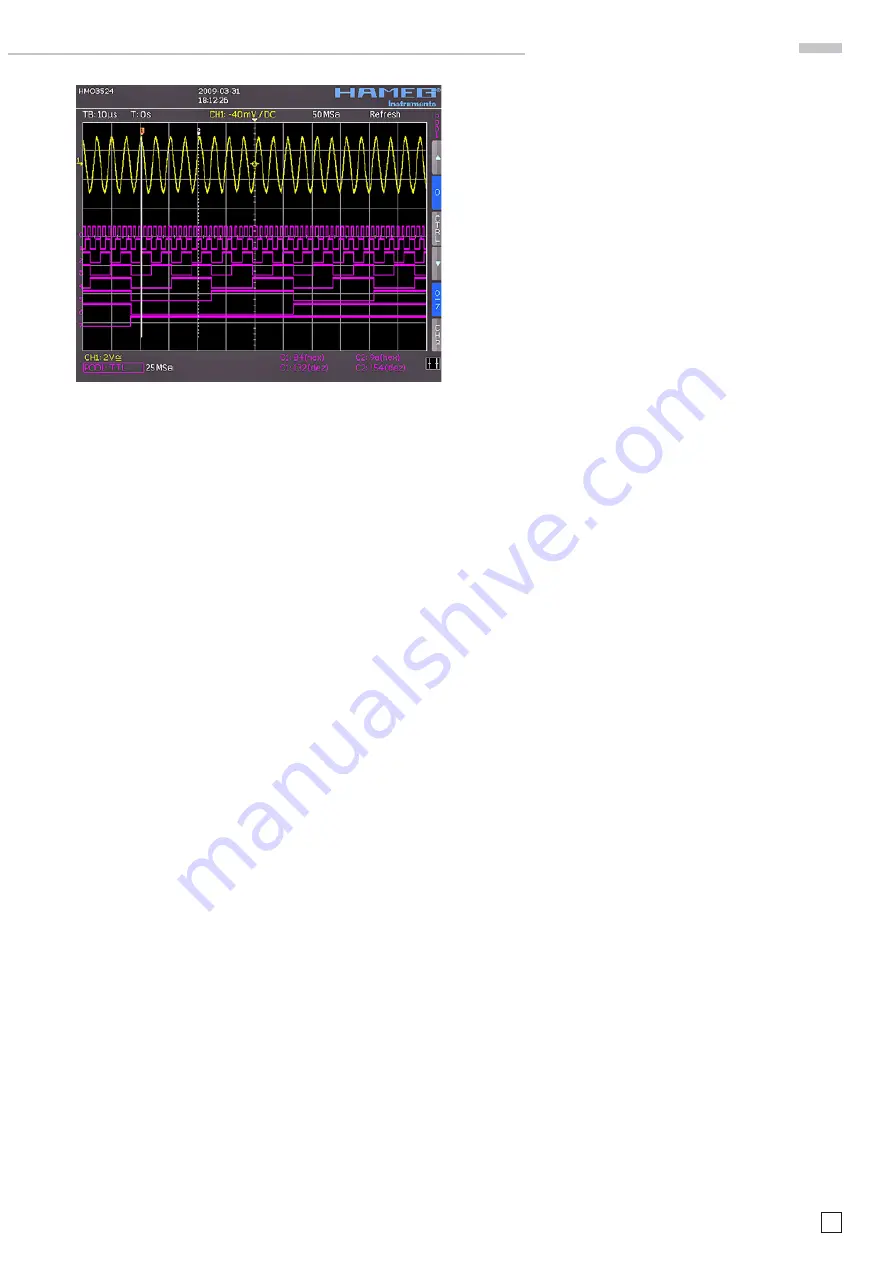
Fig. 11.2: Logic channels’ settings display
M i x e d S i g n a l O p e r a t i o n
The Y positions and the size of the logic channel displays can
be chosen as customary and known from analog channel
operation with the appropriate knobs Y-POSITION and SCALE
VOLTS/DIV (provided the soft menu key „0/7“ was selected as
indicated by a blue background). If less than 8 logic channels
are to be displayed, or if the position of individual channels is
to be changed, this can be done in the short menu in conjunc-
tion with the soft menu keys and the Y POSITION and SCALE
VOLTS/DIV controls. In order to do this, push the soft menu key
next to
CTRL
: this will allow you to control the Y position and
the size of the logic channel display with the knobs. The name
of which will be shown above the menu entry (in this example
number 0). The selection of the channels is done with the soft
keys „Arrow Up“ and „Arrow Down“. By this method all channels
may be individually positioned and sized. If POD was activated
and if the MENU key in the Channel Control section of the front
panel was pushed, the menu for setting the trigger levels will
be shown: 5 preprogrammed levels are available, 2 of which
are user defi nable.
11.3. Cursor measurements for the logic channels
If the logic channels were activated, some parameters may be
measured with the cursors. For all activated logic channels
of a POD these measurements are available: TIME, RATIO X,
V–MARKER. The results will be as follows:
TIME:
The time position of both cursors relative to the trigger time
position will be indicated; also the time difference between the
two cursor positions from which the frequency is calculated.
RATIO X:
In this mode 3 cursors are used. The time ratios between the
fi rst and the second and between the fi rst and the third will
be shown. The presentation will be in fl oating point format, in
percent, in degrees, and in radians.
V–MARKER:
With the logic channels the logic value of the selected POD will
be measured at the position of the respective cursor and shown
in hexadecimal and decimal formats.
Содержание Hameg HMO3522
Страница 1: ...350 MHz Digital Oscilloscope with FFT and mixed signal option HMO3522 3524 Manual English...
Страница 33: ...33 Subject to change without notice A p p e n d i x...
Страница 34: ...34 Subject to change without notice Appendix...
Страница 35: ...35 Subject to change without notice A p p e n d i x...


