23
Subject to change without notice
RATIO Y
This mode provides 3 cursors in order to measure ratios in Y
direction (e.g. an overshoot) between the fi rst and the second
and between the fi rst and the third cursors. The results will be
presented in 2 formats: fl oating point, percent.
COUNT:
This mode provides 3 cursors in order to count signal crossings
of a level which can be set with the third cursor for a time span as
defi ned by the distance between the fi rst and the second cursors.
The result will be presented in 4 different versions: number of
rising and falling level crossings, number of positive and negative
pulses.
PEAK LEVELS
This mode provides 2 cursors in order to measure the minimum
and maximum values of a signal within the time span as defi ned
by the two cursors. The values Vp- and Vp+ represent the mi-
nimum and maximum values of the voltage. The peak-to-peak
value (Vpp) is equal to the difference between the minimum and
maximum values.
RMS MEAN
This mode provides 2 cursors in order to calculate the rms and
the mean values of a signal between the two cursors.
RISE TIME
This mode provides 2 cursors in order to measure the rise and fall
times between the two cursors.
V MARKER
This mode provides 2 cursors in order to measure two different
voltages and a time span. The values V1 and V2 represent the
voltages between the zero base line and the respective cursor.
ΔV represents the voltage difference between the two cursors. Δt
represents the time difference between them.
The menu item
AUTO SOURCE
may be turned on or off with the as-
sociated soft menu keys
ON
and
OFF
; the active state is marked by
its blue background. If
ON
was chosen, the cursor measurements
will be executed on the active channel; this allows you to quickly
execute similar measurements on different signals. If
OFF
was
selected, measurements will always be performed on the channel
selected in the menu
SOURCE
.
By pushing the soft key next to the menu
SET
, the selected cursors
will be automatically placed on optimum positions along the signal
curve; this allows very fast and usually optimum placement of the
cursors. As mentioned earlier, the cursors may also be placed
manually with the universal knob after pushing the key CURSOR
SELECT and selecting them. In case the automatic placement
does not function with very complex signals, the cursors can be
brought to a predefi ned starting position by pushing the key next
to the menu
CENTER
. The last menu item allows you to switch the
cursors off by pushing the soft key next to it.
The key CURSOR MODE opens the menu item
GLUE TO
. This mode
can be turned on or off. If activated, the cursors will „glue to“ the
signal, i.e. they will automatically follow all changes of the position
and scaling controls and also deliver new measurement results. If
this mode is deactivated, the cursors will remain in their positions
irrespective of any repositioning or rescaling of the signals.
8.2. Auto
measurements
The HMO352x series oscilloscopes offer cursor measurements
and additionally automatic measurements. By pushing the key
AUTO MEASURE
in the ANALYZE section of the front panel the
menu will open.
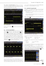
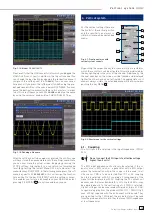
Fig. 8.2: Menu for the automatic measurements settings
This menu offers the selection of two auto measurement
functions:
MEASURE 1
and
MEASURE 2
can be switched
ON
or
OFF
with the respective soft menu keys. The associated soft
menus will open selection windows upon pushing the respec-
tive menu key. Each window will present all available kinds of
measurement which can be selected with the universal knob.
The source for the measurements can be selected with the
universal knob after pushing the respective soft menu key.
The listing of available sources will only show the displayed
channels. The results will be displayed in the right bottom
corner of the screen.
The following kinds of measurement are available:
MEAN
In this mode the mean value of the signal will be measured.
With periodic signals only the fi rst period shown on the left of
the graticule will be measured.
RMS
This mode measures and calculates the rms value of the signal
but only for those portions of the signals which are displayed.
If the signal is periodic, the fi rst period displayed will be used.
The „true rms“ value will be calculated.
COUNT +
In this mode the number of positive pulses displayed will be
counted. A positive pulse is defi ned as consisting of a rising
and a falling slope. The switching level will be calculated by
measuring the mean value of the signal. A crossing of this level
only in one direction will not be counted.
COUNT –
In this mode the number of negative pulses displayed will be
counted. A negative pulse is defi ned as consisting of a falling
and a rising slope. As before, the mean value of the signal will
be measured and used as the trigger level. A crossing of this
level only in one direction will not be counted.
COUNT +/
In this mode positive slopes of the signal within the displayed
area will be counted. As before, the mean value of the signal
will be measured and used as the trigger level.
COUNT-/
In this mode negative slopes of the signal within the displayed
area will be counted. As before, the mean value of the signal
will be measured and used as the trigger level.
M e a s u r e m e n t s
Содержание Hameg HMO3522
Страница 1: ...350 MHz Digital Oscilloscope with FFT and mixed signal option HMO3522 3524 Manual English...
Страница 33: ...33 Subject to change without notice A p p e n d i x...
Страница 34: ...34 Subject to change without notice Appendix...
Страница 35: ...35 Subject to change without notice A p p e n d i x...


