background image

Interfaces and Connectors

R&S

®

SFE100

23

Getting Started 2112.4122.62 ─ 13

Table 5-2: Pin assignment

Pin

Description

1

Ground

2

Ground

3

AF2


- (Audio IN)

4

AF2


+ (Audio IN)

5

BTSC IN

6

AF1


- (Audio IN)

7

AF1


+ (Audio IN)

8

REF FREQ OUT


/ Trigger Out

9

NICAM IN

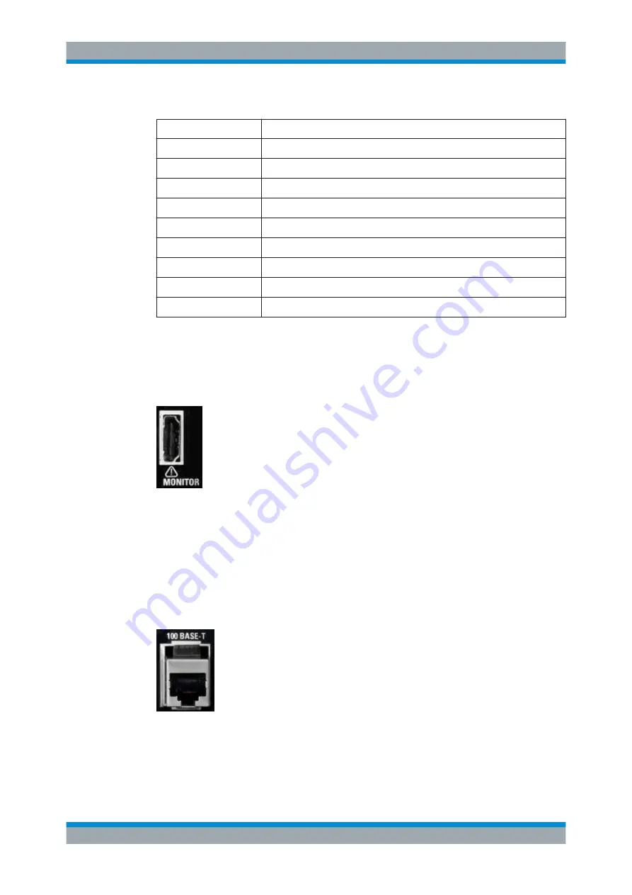
5.2.5 MONITOR

HDMI interface to connect an external monitor. For further details refer to 

Chap-

ter 6.3.4, "External Monitor"

on page 31.

5.2.6 100 BASE-T

1 Gigabit LAN interface (100


Base-T).

Used to connect the R&S


SFE100 to a local network for remote control, remote opera-

tion, printouts and data transfer. The assignment of the RJ.45 CAT5 connector sup-
ports twisted pair category 7 UTP/STP cables in a star configuration (UTP stands for
"unshielded twisted pair", and STP for "shielded twisted pair").


Rear Panel

Содержание 2112.4100.02

Страница 1: ...R S SFE100 Test Transmitter Getting Started Getting Started 2112 4122 62 13 E YF...

Страница 2: ...m product sfe100 html Downloads Firmware Rohde Schwarz would like to thank the open source community for their valuable contribution to embedded computing 2017 Rohde Schwarz GmbH Co KG M hldorfstr 15...

Страница 3: ...e of the product The product is used for its designated purpose if it is used in accordance with its product documentation and within its performance limits see data sheet documentation the following...

Страница 4: ...ation item 7 Signal words and their meaning The following signal words are used in the product documentation in order to warn the reader about risks and dangers Indicates a hazardous situation which i...

Страница 5: ...afety is not observed either at all or to the extent necessary electric shock fire and or serious personal injury or death may occur 1 Prior to switching on the product always ensure that the nominal...

Страница 6: ...t be fuse protected in such a way that anyone who has access to the product as well as the product itself is adequately protected from injury or damage 14 Use suitable overvoltage protection to ensure...

Страница 7: ...masks and protective clothing must be worn 7 Laser products are given warning labels that are standardized according to their laser class Lasers can cause biological harm due to the properties of the...

Страница 8: ...ckaging until they are ready to be used 4 Cells and batteries must not be exposed to any mechanical shocks that are stronger than permitted 5 If a cell develops a leak the fluid must not be allowed to...

Страница 9: ...National waste disposal regulations must be observed 4 If handling the product releases hazardous substances or fuels that must be disposed of in a special way e g coolants or engine oils that must b...

Страница 10: ...ien las informaciones de seguridad elementales as como la documentaci n del producto y entr guelas a usuarios posteriores Tener en cuenta las informaciones de seguridad sirve para evitar en lo posible...

Страница 11: ...raves o incluso la muerte Indica una situaci n de peligro que si no se evita puede causar lesiones graves o incluso la muerte Indica una situaci n de peligro que si no se evita puede causar lesiones l...

Страница 12: ...entaci n del producto o en la hoja de datos En caso de sobrecalentamiento del producto pueden producirse choques el ctricos incendios y o lesiones graves con posible consecuencia de muerte Seguridad e...

Страница 13: ...0950 1 EN60950 1 o IEC61010 1 EN 61010 1 v lidos en cada caso 11 A menos que est permitido expresamente no retire nunca la tapa ni componentes de la carcasa mientras el producto est en servicio Esto p...

Страница 14: ...manipulaci n mec nica y o t rmica o el desmontaje del producto debe tenerse en cuenta imprescindiblemente el cap tulo Eliminaci n protecci n del medio ambiente punto 1 5 Ciertos productos como p ej la...

Страница 15: ...a las bater as y acumuladores o celdas pueden producirse explosiones incendios y o lesiones graves con posible consecuencia de muerte El manejo de bater as y acumuladores con electrolitos alcalinos p...

Страница 16: ...sin clasificar sino que debe ser recogido por separado La eliminaci n se debe efectuar exclusivamente a trav s de un punto de recogida apropiado o del servicio de atenci n al cliente de Rohde Schwarz...

Страница 17: ...ies never shift the instrument when its feet are folded out The overall load the instrument s own weight plus that of the instru ments stacked on top of it on the folded out feet must not exceed 500 N...

Страница 18: ...con los telepi s desdoblados para evitar heridas El peso total equilibrado peso pr pio m s el de los aparatos posicio nados sobre este ejercido sobre los telepi s no deber exceder a los 500 N Posicio...

Страница 19: ...he instruments according to their size with the largest instrument on the bottom Do not stack more than three in struments directly on top of each other Instruments may only be stacked if their feet a...

Страница 20: ...s por orden de su tama o No amontonar nunca m s de tres aparatos uno sobre el otro Los aparatos solamente deber n ser amontonados si los pi s y la caja del aparato correspondiente hacen posible amonto...

Страница 21: ...ument up to date and to be informed about new application notes related to your instrument please send an e mail to the Customer Support Center stating your instrument and your wish We will take care...

Страница 22: ...tion Cards White Papers etc 10 3 System Overview 11 3 1 Basic Instrument Concept 11 3 1 1 Baseband Section 12 3 1 2 RF Section 13 4 Setting Up the R S SFE100 14 4 1 Unpacking the R S SFE100 14 4 1 1 I...

Страница 23: ...reventing Electromagnetic Interference 28 6 2 Connecting to the AC Power Supply 28 6 3 Connecting External Devices 29 6 3 1 External Keyboard 30 6 3 2 Mouse 31 6 3 3 Memory Stick 31 6 3 4 External Mon...

Страница 24: ...1 Login 49 10 1 2 Windows XP Start Menu 50 10 2 Additional Software 50 10 3 Windows XP Recovery and Backup Partition 50 10 3 1 Performing Backup Recovery 50 10 3 2 Recommended Procedure for the R S S...

Страница 25: ...Contents R S SFE100 6 Getting Started 2112 4122 62 13...

Страница 26: ...ed as follows In the Basic Safety Instructions safety issues are grouped according to subjects For example one subject is electrical safety The Basic Safety Instructions are delivered with the R S SFE...

Страница 27: ...ventions for procedure descriptions When describing how to operate the R S SFE100 several alternative methods may be available to perform the same task If possible the procedure using the front panel...

Страница 28: ...ing examples and information on maintenance instrument interfaces and error messages Includes the contents of the getting started manual The contents of the user manual is available as help in the R S...

Страница 29: ...elease notes list new features improvements and known issues of the current firmware version and describe the firmware installation The open source acknowledgment document provides verbatim license te...

Страница 30: ...n You can easily switch operating parameters e g roll off puncturing rate QAM mode and select operating parameters whose values exceed those defined in the standard for lab applications For special ta...

Страница 31: ...ng and processing I Q signals It is entirely digital in design Depending on the R S SFE100 model the baseband section provides all of the trans port stream TS interfaces and handles processing of the...

Страница 32: ...ch are forwarded to the RF section Using the AWGN software option R S SFE100 K40 noise generator additive white Gaussian noise AWGN can be generated 3 1 2 RF Section The D A converter converts the dig...

Страница 33: ...hipping container and cushioning material for damage 2 Unpack the cardboard box see Chapter 4 1 Unpacking the R S SFE100 on page 14 and check the housing and handle for visible damages or loose parts...

Страница 34: ...re unobstructed and the airflow perforations are unimpeded The minimum distance from the wall is at least 10 cm Failure to meet these conditions may cause damage to the R S SFE100 or other devi ces in...

Страница 35: ...112 4122 62 13 4 2 2 Mounting the R S SFE100 in a Rack The R S SFE100 may be installed in a 19 rack mount by using a rack adapter kit for order no see data sheet Follow the installation instructions t...

Страница 36: ...etic interfer ence For details see Chapter 6 1 Preventing Electromagnetic Interference on page 28 5 1 Front Panel This chapter provides an overview of the controls and connectors on the front panel Ea...

Страница 37: ...ric parameters the unit is also displayed Switches the marked status parameters on off State On Off Confirms OK and closes message windows RF ON OFF Switches the RF output on or off LOCAL Switches fro...

Страница 38: ...meter For further details see user manual or the help system 5 1 4 Display Only provided by the models 02 and 03 See 4 in Figure 5 1 For details on using the front panel display see the user manual or...

Страница 39: ...External Devices on page 29 or to perform a firm ware update Upper connector port 1 Lower connector port 3 Electromagnetic interference EMI can affect the measurement results To avoid any impact make...

Страница 40: ...he AC power connector Switch positions I The R S SFE100 is in operation O The entire instrument is disconnected from the AC power supply For further information See Chapter 11 2 Replacing the Fuses on...

Страница 41: ...nnector Video input for the ATV transmission standards 5 2 4 AUDIO AUX 9 pin SUB D connector for multi purpose input Audio IN BTSC IN NICAM IN REF FREQ OUT Trigger OUT A signal is present on the refer...

Страница 42: ...o connect an external monitor For further details refer to Chap ter 6 3 4 External Monitor on page 31 5 2 6 100 BASE T 1 Gigabit LAN interface 100 Base T Used to connect the R S SFE100 to a local netw...

Страница 43: ...100 in a LAN on page 45 See user manual or the help system for remote control using the Ethernet Table 5 3 Pin assignment Pin Abbreviation Signal 1 TXD Transmit data positive 2 TXD Transmit data negat...

Страница 44: ...G_IQ_IN_D5 Data bit OUT IN 5 line I Q signal 12 DIG_IQ_IN_D6 Data bit OUT IN 6 line I Q signal 13 DIG_IQ_IN_D7 Data bit MSB OUT IN 7 line I Q signal 14 DIG_IQ_CLK2 Data clock 2 control signal 15 DIG_I...

Страница 45: ...tails see Chapter 5 1 6 USB Interfaces on page 20 5 2 9 REF IN BNC connector Used to input the reference frequency For further details see user manual or the help system 5 2 10 1PPS TRIG BNC connector...

Страница 46: ...Interfaces and Connectors R S SFE100 27 Getting Started 2112 4122 62 13 Rear Panel...

Страница 47: ...f double shielded cables USB interfaces To connect the USB interfaces only use peripheral equipment that does not cause limit violations For details see Chapter 5 1 6 USB Interfaces on page 20 HDMI in...

Страница 48: ...by using USB hubs Due to the large number of available USB devices there is almost no limit to the possi ble expansions In the following USB devices that can be useful are listed Keyboard for entering...

Страница 49: ...ponding keys front panel external keyboard model 02 03 Key on front panel Corresponding key on key board Function description Cursor keys LEFTARROW RIGHTARROW UPARROW DNARROW See Chapter 5 1 3 Cursor...

Страница 50: ...e speed of the mouse cursor in Windows XP Changing Mouse Settings 1 Open the Start menu by pressing the WINDOWS key on an external keyboard 2 Select Control Panel and then Mouse 6 3 3 Memory Stick The...

Страница 51: ...HDMI interface by pressing the CTRL ALT F4 key combination several times if necessary For R S SFE100s without HDMI interface it is possible to display the screen contents on external monitors by using...

Страница 52: ...y cause damage to the R S SFE100 or other devices in the test setup To switch on the R S SFE100 1 Make sure that the R S SFE100 is connected to a power supply for details see Chapter 6 2 Connecting to...

Страница 53: ...FE100 to the O position None of the LEDs on the front panel should be lit 7 3 Checking the Provided Options The R S SFE100 may be equipped with options In order to check whether the instal led options...

Страница 54: ...r press the ERROR WARNING DETAILS softkey A description of the error s or warning s is displayed For further details see the user manual or the help system Besides automatic monitoring of instrument f...

Страница 55: ...Devices on page 29 or operate the R S SFE100 using an external com puter you can use the graphical user interface The following step by step instructions describe how to perform the sample applicatio...

Страница 56: ...ect the FREQUENCY submenu 4 Press the ENTER key The focus is set on the work view 5 Set a frequency of 330 MHz a Select the FREQUENCY field b Enter 330 c Press the ENTER key The entered frequency is d...

Страница 57: ...c Press the ENTER key d If you want to enter the level in a different unit change the unit in the LEVEL menu under SETTINGS LEVEL UNIT first see user manual or help sys tem The entered level is displ...

Страница 58: ...GNAL SOURCE field b Press the ENTER key to display the list c Depending on the R S SFE100 model if not fixed select DIGITAL TV d Press the ENTER key to confirm the selection 7 Depending on the install...

Страница 59: ...ed See Figure 8 1 3 In the tree select the INPUT SIGNAL submenu 4 Press the ENTER key The focus is set on the work view Figure 8 1 DIGITAL TV menu 5 Select the EXTERNAL signal source a Select the SOUR...

Страница 60: ...rate of 6 9 MS s a Select the SYMBOL RATE field b Enter 6 9 c If the units field to the right shows MS s press the ENTER key d If the units field indicates another unit select this field Press the ENT...

Страница 61: ...UPARROW DNARROW keys change the numeric value to 330 MHz 8 Press OK to confirm your entry 9 Press the BACK key to exit the work view and get back to the tree Setting the output level 1 Using the UPARR...

Страница 62: ...the EXTERNAL source a Using the UPARROW DNARROW keys select the SOURCE field b Press OK to open the list c Using the UPARROW DNARROW keys select EXTERNAL d Press OK to confirm your entry 5 Select the...

Страница 63: ...Using the UPARROW DNARROW keys change the numeric value to 6 9 MS s d Press OK to confirm your entry 10 Select the 64QAM constellation a Using the UPARROW DNARROW keys select the CONSTELLATION field b...

Страница 64: ...ll these administration tasks are normally performed by a network administrator using the Windows XP Start menu for details refer to the Windows XP help system Contact your network administrator for a...

Страница 65: ...twork a LAN connection between an R S SFE100 and a single computer without integration into a larger network an IP address needs to be assigned to the R S SFE100 and the computer The IP addresses 192...

Страница 66: ...a unique computer name Every instrument is assigned an individual computer name at the factory It is displayed as part of the window title of the application If necessary you can change the computer n...

Страница 67: ...tect the R S SFE100 from an attack of hostile users and programs The Windows Firewall suppresses all network communication which is not initialized by the R S SFE100 itself or which is not defined as...

Страница 68: ...settings do not conform to the default settings Risk of causing instrument unusability To prevent malfunctions and to avoid instrument repair only install service packs approved by Rohde Schwarz In pa...

Страница 69: ...released by Rohde Schwarz 10 3 Windows XP Recovery and Backup Partition The R S SFE100 provides a backup and recovery partition A backup of the factory system partition C is stored per default and ca...

Страница 70: ...ed and the reg ular boot process continues After pressing OK within 4 seconds the recovery process starts and the following message is displayed Restore in progress Please wait After the restore proce...

Страница 71: ...artition factory version is started see Important infor mation for the R S SFE100 models 02 03 on page 53 R S SFE100 models 12 13 The Windows XP Recovery and Backup Embedded Partition dialog is displa...

Страница 72: ...nly if the installed image is older than LPCx_SFE_0024 you must not select Factory Default to avoid problems due to interference with the running background process For R S SFE100 models 12 13 continu...

Страница 73: ...nd Backup Partition dialog is displayed again 3 Click Exit and Shutdown 4 Turn off on the R S SFE100 manually 10 3 3 2 Recovering the Selected Version of System Partition Only R S SFE100 models 12 13...

Страница 74: ...nly R S SFE100 models 12 13 1 In the Windows XP Embedded Recovery and Backup Partition dialog see To display the Windows XP Embedded Recovery and Backup Partition dialog on page 51 click Factory Defau...

Страница 75: ...p Partition dialog on page 51 click Remove Backup to delete a selected backup The Remove Backup dialog is displayed It shows the versions of the firmware and the software platform of the selected back...

Страница 76: ...ck the rated data from time to time If any problem arises contact one of our customer support centers The addresses of our customer support centers are provided at the beginning of this manual 11 1 Cl...

Страница 77: ...e fuse holder back in its slot and close the lid 11 3 Storing the Instrument The storage temperature range of the R S SFE100 is given in the data sheet If the R S SFE100 is to be stored for a longer p...

Страница 78: ...21 USB 20 26 VIDEO IN 22 Conventions 7 Cursor keys 19 D Data sheets 10 Deleting system partition backups 56 Designated purpose 7 DIG I Q IN connector 24 Display 19 DNARROW key 19 Documentation overvie...

Страница 79: ...atus display 18 RF ON OFF hardkey 18 RF OUT connector 19 26 RIGHTARROW key 19 S Safety information 7 Safety instructions 9 Shipping damage inspection 14 Software installing 50 Software options install...

Отзывы: