background image

Parameter Descriptions

11-73

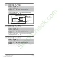
Parameter number whose value will be written from a network 
communications device data table.

Parameters that can only be changed while the drive is stopped 
cannot be used as Datalink inputs. Entering a parameter of this type 
will disable the link.

Refer to the appropriate communications option board manual for 
Datalink information.

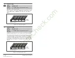
Parameter number whose value will be written from a 
communications device data table.

Parameters that can only be changed while the drive is stopped 
cannot be used as Datalink inputs. Entering a parameter of this type 
will disable the link.

Refer to the appropriate communications option board manual for 
Datalink information.

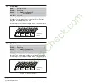
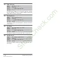
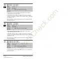
300
301

Data In A1 

- Link A Word 1

Data In A2

 - Link A Word 2

Range:

0 to 387   [1]

Default:

0 (Disabled)

Access:

2

Path: 

Communication>Datalinks

See also:

Network

Network
Card

Data

P#

SP600

Data In

(parameter #)

Data Received by Drive from Network

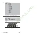
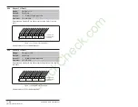
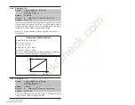
302
303

Data In B1 

- Link B Word 1

Data In B2

 - Link B Word 2

Range:

0 to 387   [1]

Default:

0 (Disabled)

Access:

2

Path: 

Communication>Datalinks

See also:

StockCheck.com

Downloaded from StockCheck.com

Содержание Reliance electric 6SB401 Series

Страница 1: ...Instruction Manual SP600 AC Drive User Manual Version 3 0 6SB401 Series 20 HP to 200 HP 460 VAC 20 HP to 150 HP 575 VAC D2 3501 5 S t o c k C h e c k c o m ...

Страница 2: ...ensure the DC bus capacitors are discharged before touching any internal components Failure to observe this precaution could result in severe bodily injury or loss of life ATTENTION The drive can operate at and maintain zero speed The user is responsible for assuring safe conditions for operating personnel by providing suitable guards audible or visual alarms or other devices to indicate that the ...

Страница 3: ...utotune 2 8 2 3 12Drive Protection Current Limit 2 8 2 3 13Drive Overload Protection 2 9 2 3 14Motor Overload Protection 2 10 2 3 15 Shear Pin Fault 2 10 2 3 16 Drives Peripheral Interface DPI 2 10 2 3 17Network Data Transfer via Datalinks 2 11 2 3 18Programmable Parameter Access Levels and Protection 2 11 2 3 19Process PI Loop 2 11 2 3 20S Curve 2 12 2 3 21Three Skip Bands Avoidance Frequencies 2...

Страница 4: ...he Drive s Watts Loss Rating 3 11 Chapter 4 Wiring Requirements for the Drive 4 1 Power Wiring 4 1 4 1 1 Power Wire Sizes 4 3 4 1 2 Using Input Output Contactors 4 4 4 2 Control and Signal Wire Sizes 4 5 4 3 Recommended Motor Lead Lengths 4 5 4 3 1 Reflected Wave Compensation 4 6 4 4 Selecting Input Line Branch Circuit Protection 4 9 4 5 Verifying Power Module Output Current Rating is Greater than...

Страница 5: ...apter 9 Using the Start Up Routines on the LCD OIM 9 1 Preparing for Start Up 9 1 9 2 Running the Start Up Routines 9 2 9 2 1 Sensorless Vector Performance 9 4 9 2 2 High Speed Operation 120 Hz 9 5 9 3 Start Stop Control 9 5 9 4 Speed Reference 9 6 9 5 Changing the Speed of the Drive Setpoint Control 9 6 Chapter 10 Programming Basics 10 1About Parameters 10 1 10 2How Parameters are Organized 10 2 ...

Страница 6: ...ve Using the LCD OIM 12 23 12 8 1Accessing the Fault Queue 12 24 12 8 2Accessing the Fault Parameters 12 25 12 8 3Accessing the Drive Status Parameters 12 25 12 8 4Determining the Product Version 12 26 12 8 5Contacting Tech Support for Assistance 12 28 Appendix A Technical Specifications Appendix B Using the LCD OIM Appendix C Parameters Cross Referenced by Name Appendix D Analog Input Selection P...

Страница 7: ...ns Frame 2 Shown 5 2 Figure 5 2 Wire Routing and Terminal Block Locations Frame 5 Shown 5 3 Figure 5 3 Typical Grounding 5 4 Figure 5 4 Single Point Grounding Panel Layout 5 5 Figure 6 1 Opening the Drive Cover 6 1 Figure 6 2 Power Terminal Block 6 5 Figure 7 1 Typical Wiring Diagram 7 7 Figure 7 2 Wiring Diagram Default Drive Configuration 7 9 Figure 7 3 Speed Reference Control Flowchart 7 11 Fig...

Страница 8: ...11 24 Dig Out Status 217 11 63 Figure 11 25 Status 1 Fault 227 11 65 Figure 11 26 Status 2 Fault 228 11 65 Figure 11 27 Alarm 1 Fault 229 11 66 Figure 11 28 Alarm 2 Fault 230 11 66 Figure 11 29 Fault Config 1 238 11 68 Figure 11 30 Alarm Config 1 259 11 69 Figure 11 31 Drive Logic Rslt 271 11 70 Figure 11 32 Manual Mask 286 11 71 Figure 11 33 Stop Owner 11 72 Figure 11 34 Manual Owner 11 72 Figure...

Страница 9: ...omponent Levels 12 26 Figure 12 11 Accessing the OIM Version Information 12 27 Figure 12 12 OIM Version Screens at the Product and Component Levels 12 27 Figure 12 13 Accessing the Device Item Information 12 27 S t o c k C h e c k c o m Downloaded from StockCheck com ...

Страница 10: ...VIII SP600 AC Drive User Manual S t o c k C h e c k c o m Downloaded from StockCheck com ...

Страница 11: ...rameter Configuration for Figure 7 1 Wiring Example 7 8 Table 9 1 Quickstart Parameters 9 3 Table 11 1 Parameter List 11 2 Table 11 2 Default Values for Preset Speeds 1 7 11 25 Table 11 3 Sleep Wake Mode 11 47 Table 11 4 Dynamic User Set Mode 11 56 Table 11 5 Analog Output Scaling 11 82 Table 11 6 Speed Select Inputs 11 84 Table 11 7 Default Values for Parameters 361 366 11 84 Table 11 8 Drive Res...

Страница 12: ... Speed Command 12 21 Table 12 12 Motor and or Drive Will Not Accelerate to Commanded Speed 12 22 Table 12 13 Motor Operation is Unstable 12 22 Table 12 14 Stopping the Drive Results in a Decel Inhibit Fault 12 23 Table 12 15 OIM Cables 12 23 Table 12 16 Drive Unit 12 23 S t o c k C h e c k c o m Downloaded from StockCheck com ...

Страница 13: ...parameter name followed by the parameter number For example PI Control 125 1 2 Getting Assistance from Reliance Electric If you have any questions or problems with the products described in this instruction manual contact your local Reliance Electric sales office For technical assistance call 1 864 284 5444 Before calling please review the troubleshooting section of this manual and check the stand...

Страница 14: ...1 2 SP600 AC Drive User Manual S t o c k C h e c k c o m Downloaded from StockCheck com ...

Страница 15: ...ormation on identifying the drive Descriptions of NEMA ratings Descriptions of features A description of drive connections and communication options 2 1 Identifying the Drive by Model Number Each SP600 AC drive can be identified by its model number as shown in figure 2 1 The model number is on the shipping label and the drive nameplate The model number includes the drive and any factory installed ...

Страница 16: ...77 77 A 60 HP 45KW 096 96 A 75 HP 55 kW 125 125 A 100 HP 55 kW 156 156 A 125 HP 90 KW 180 180 A 150 HP 110 KW 248 248 A 200 HP 132 KW 575 VAC 022 22 A 20 HP 15 kW 027 27 A 25 HP 18 5 kW 032 32 A 30 HP 22 kW 041 41 A 40 HP 30 kW 052 52 A 50 HP 37 kW 062 62 A 60 HP 45 kW 077 77 A 75 HP 55 kW 099 99 A 100 HP 75 kW 125 125 A 125 HP 90 kW 144 144 A 150 HP 110 kW A 24 VDC I O Card B 120 VAC I O Card Res...

Страница 17: ...04 72 84 112 37 50 30 40 49 6 59 6 717 077xxxxx 4 77 97 5 130 85 108 144 45 60 37 50 60 1 72 3 974 096xxxxx 5 96 106 144 105 116 158 55 75 74 9 90 1 1146 77 116 154 85 128 170 45 60 60 1 72 3 974 125xxxxx 5 125 138 163 125 138 163 55 100 97 6 117 1475 96 144 168 96 144 168 45 75 74 9 90 1 1146 156xxxxx 6 156 172 234 170 187 255 93 125 1 122 147 1827 125 188 250 140 210 280 75 100 109 131 1475 180x...

Страница 18: ...del Number Frame Output Amps Nominal Power Ratings Input KVA 575 VAC Input Amps 575 VAC Watts Loss 4 kHz 575 VAC 575 VAC 110 OL Duty 150 OL Duty Cont 1 Min 3 Sec kW HP kW HP 022xxxxx 2 22 25 5 34 15 20 11 15 20 1 20 2 334 027xxxxx 2 27 33 44 18 5 25 15 20 24 7 24 8 376 032xxxxx 3 32 40 5 54 22 30 18 5 25 29 3 29 4 408 041xxxxx 3 41 48 64 30 40 22 30 37 4 37 6 552 052xxxxx 3 52 61 5 82 37 50 30 40 ...

Страница 19: ...rce for the analog output by setting Analog Out1 Sel 342 Refer to parameter 342 in chapter 11 for the analog output source options 2 3 3 Digital Outputs The SP600 drive provides two relay outputs for external annunciation of a variety of drive conditions Each relay is a Form C 1 N O 1 N C with shared common device whose contacts and associated terminals are rated for a maximum of 250 VAC or 220 VD...

Страница 20: ... in an attempt to maintain motor shaft speed within the specified regulation percentage The Speed Mode parameter 80 selects the speed regulation method for the drive and can be set to one of 3 choices Open Loop No speed control is offered Slip Comp Slip Compensation is active Process PI The PI loop sets the actual speed based on process variables Refer to parameter 80 in chapter 11 for more inform...

Страница 21: ... MOP Ref parameter 194 MOP Frequency parameter 11 MOP increment input parameters 361 to 366 MOP decrement input parameters 361 to 366 2 3 10 Auto Restart Reset Run The Auto Restart feature enabled in parameter 174 Auto Rstrt Tries provides the ability for the drive to automatically perform a fault reset followed by a start attempt without user or application intervention This allows for automatic ...

Страница 22: ...offset the voltage drop developed across the stator resistance An accurate calculation of the IR Voltage Drop will ensure higher starting torque and better performance at low speed operation If it is not possible or desirable to run the Autotune tests there are two other methods for the drive to determine the IR Voltage Drop and Flux Current parameters One method retrieves the default parameters s...

Страница 23: ...ure rises the drive may lower the PWM frequency to decrease the switching losses in the IGBT If the temperature continues to rise the drive may reduce current limit to try to decrease the load on the drive If the drive temperature becomes critical the drive will generate a fault If the drive is operated in a low ambient condition the drive may exceed rated levels of current before the monitored te...

Страница 24: ...ve output current exceeds the programmed current limit see parameter 238 As a default exceeding the set current limit is not a fault condition However if you want to stop the process in the event of excess current the Shear Pin feature can be activated By programming the drive current limit value and enabling the electronic shear pin the drive will fault if excess current is demanded by the motor ...

Страница 25: ... Levels and Protection The SP600 drive allows you to limit the number of parameters that can be viewed on the LCD OIM using an Access Level password By limiting the parameter view to the most commonly adjusted set additional features that may make the drive seem more complicated are hidden If you are trying to gain access to a particular parameter and the OIM skips over it you must change the para...

Страница 26: ...in parameter 169 is used to start into a rotating motor as rapidly as possible and resume normal operation with a minimal impact on load or speed This action will prevent an overcurrent trip and significantly reduce the time for the motor to reach its desired frequency Since the motor is picked up smoothly at its rotating speed and ramped to the proper speed little or no mechanical stress is prese...

Страница 27: ...tor and drive selection is required to minimize the potential risks 2 3 25 Economizer Mode Economize mode consists of operating the drive in sensorless vector control mode with an energy saving function E SVC When the drive is in this mode and operating at steady state output frequency the output voltage is automatically adjusted as the load is increased or decreased This is done so that minimum c...

Страница 28: ... parameter settings in a specific EEPROM area known as a user set Up to three user sets can be stored in the drive s memory to be used for backup batch switching or other needs All parameter information is stored You can then recall this data to the active drive operating memory as needed Each user set can also be identified with a user selected name You can use this feature using any of the follo...

Страница 29: ...rage Changes made to parameter values while Dynamic Mode is active will not be saved Parameter changes or power loss while Dynamic Mode is disabled Normal Mode will still automatically save changed data to active area non volatile storage Loading of User Set data to operating memory can occur only while the drive is in a stop condition If a Dynamic Mode command from digital inputs occurs while the...

Страница 30: ...er changes will be lost When Dyn UserSet Cnfg 204 is set to Enabled the drive will immediately transfer the selected User Set to operating memory as determined by digital inputs or DynUsrSetSel 205 The drive will verify that the User Set digital input configuration is identical in all three sets To avoid operational conflict between User Set values all digital inputs must be set identically in eac...

Страница 31: ... Second Environment Adjustable speed electrical power drive systems Part 3 EMC product standard including specific test methods General Notes To be CE compliant the motor cable should be kept as short as possible in order to avoid electromagnetic emission as well as capacitive currents AC drives may cause radio interference The user is required to take measures to prevent interference If the adhes...

Страница 32: ... filters per table 2 2 Table 2 3 SP600 AC Drive EN1800 3 EMC Compatibility Frame Drive Description Second Environment First Environment Restricted Distribution 2 Drive with any options Restrict Motor Cable to 30 m 98 ft Restrict Motor Cable to 150 m 492 ft Install external filter1 1 Select the Deltron Emcom http www deltron emcom com filter or equivalent that meets your specifications from the lis...

Страница 33: ...rive Connections No Connector Description Power Terminal Block Connections for input and output power wiring Signal and I O Terminal Block Connections for signal and I O wiring Important The I O board may be 24 VDC or 115 VAC Check the model number on the drive nameplate DPI Port 1 OIM connection DPI Port 2 Connection for remote OIM or RECOMM 232 serial interface DPI Port 5 Connection for optional...

Страница 34: ... PS PS WIRE RANGE 22 10 AWG 0 5 4 MM2 TORQUE 5 3 IN LB 0 6 N M STRIP LENGTH 0 35 IN 9 MM 17 21 INPUT AC OUTPUT Optional Communications Module 9 Frame 5 Optional Communications Module L2 L1 T3 T2 T1 L3 INPUT OUTPUT USE 75 C COPPER WIRE ONLY TORQUE 52 IN LB 6 N M BR2 PS PS BR1 DC DC USE 75 C COPPER WIRE ONLY TORQUE 52 IN LB 6 N M 22 10 AWG 5 3 IN LB 0 6 N M WIRE STRIP Frame 6 BR1 BR2 DC DC U T1 V T2...

Страница 35: ...t the bottom of the drive frame labeled in figure 2 2 Note that you must change the appropriate parameters 89 and 90 to enable control from the remote keypad Table 2 5 Standard Kits and Options Description Model Number Instruction Manual DeviceNet Communication Module RECOMM DNET D2 3478 Profibus Communication Module RECOMM PBUS D2 3479 Interbus Communication Module RECOMM IBUS D2 3480 ControlNet ...

Страница 36: ... enables you to upload and download parameter configurations Table 2 7 PC Based Utility Model Number and Instruction Manual Number Description Model Number Instruction Manual VS Utilities RECOMM VSU232 D2 3488 Serial Converter included with VS Utilities for DPI Drives RECOMM 232 D2 3477 S t o c k C h e c k c o m Downloaded from StockCheck com ...

Страница 37: ...pplicable manuals in their entirety before proceeding Failure to observe this precaution could result in severe bodily injury or loss of life ATTENTION Use of power correction capacitors on the output of the drive can result in erratic operation of the motor nuisance tripping and or permanent damage to the drive Remove power correction capacitors before proceeding Failure to observe this precautio...

Страница 38: ...imum of 600 volts nominal 3 1 1 1 Unbalanced or Ungrounded Distribution Systems For ungrounded distribution systems disconnect the MOVs and common mode capacitors by removing or disconnecting the jumper s shown in figure 3 1 ATTENTION To guard against personal injury and or equipment damage caused by improper fusing or circuit breaker selection use only the recommended line fuses circuit breakers ...

Страница 39: ...Typical Jumper Locations BR1 BR2 DC DC U T1 V T2 W T3 SHLD SHLD PE R L1 S L2 T L3 PE 2 MOV PE JMPR PE 1 AUX IN AUX OUT 75C Cu Wire 6 AWG 10MM2 Max 12 IN LBS 1 4 N M TORQUE WIRE STRIP CONTROL POWER PE 4 PE 3 DC FILTER CAP PE JMPR Frame 2 Frame 5 BR1 BR2 DC DC U T1 V T2 W T3 R L1 S L2 T L3 PE B PE A 75C Cu Wire 3 AWG 25MM 2 Max 16 IN LBS 1 8 N M TORQUE WIRE STRIP CONTROL POWER AUX IN SHLD SHLD PE 75...

Страница 40: ...ch the input line voltage to the internal fan voltage If your line voltage is different than the voltage class specified on the drive nameplate it will be necessary to change the transformer tap as shown in figure 3 2 Common Bus DC Input drives require user supplied 120 or 240V AC to power the cooling fans The power source is connected between 0 VAC and the terminal corresponding to your source vo...

Страница 41: ...erify that the drive location will meet the environmental conditions in Appendix A Figure 3 2 Selecting Input Phase and Fan Voltage 60HP and Larger 480 Volt Tap 600 Volt Tap 690 Volt Tap 400 Volt Tap WIRE RANGE 14 1 0 AWG 2 5 35 MM2 TORQUE 32 IN LB 3 6 N M STRIP LENGTH 0 67 IN 17 MM USE 75 C CU WIRE ONLY POWER TERMINAL RATINGS WIRE RANGE 6 1 0 AWG 16 35 MM2 TORQUE 44 IN LB 5 N M STRIP LENGTH 0 83 ...

Страница 42: ...rives directly above each other Note that no devices are to be mounted behind the drive This area must be kept clear of all control and power wiring See figure 3 3 for recommended air flow clearances Figure 3 3 Minimum Mounting Clearances 101 6 mm 4 0 in 101 6 mm 4 0 in 50 8 mm 2 0 in with adhesive label without adhesive label S t o c k C h e c k c o m Downloaded from StockCheck com ...

Страница 43: ...AC 20 to 25 575 VAC 342 5 13 48 222 0 8 74 200 0 7 87 320 12 6 192 0 7 56 12 52 27 6 3 30 to 50 460 VAC 30 to 50 575 VAC 517 5 20 37 222 0 8 74 200 0 7 87 500 19 7 192 0 7 56 18 55 40 9 Figure 3 4 Panel Mount Drive Dimensions Frames 2 and 3 D W C 15 0 0 59 5 8 0 23 dia 5 5 0 22 A B 5 5 0 22 H HOT surfaces can cause severe burns CAUTION Dimensions in mm in Front View Side View Weight in kg lb S t o...

Страница 44: ... 66 201 7 7 94 738 2 29 06 192 0 7 56 24 49 54 0 Figure 3 5 Panel Mount Drive Dimensions Frame 4 A 8 0 0 31 H 7 0 0 28 dia 7 0 0 28 3 Places W C 15 0 0 59 Lifting Holes 4 Places D Dimensions in mm in Front View Side View Weight in kg lb S t o c k C h e c k c o m Downloaded from StockCheck com ...

Страница 45: ...2 16 275 4 10 84 625 0 24 61 225 0 8 86 37 19 82 0 Figure 3 6 Panel Mount Drive Dimensions Frame 5 HOT surfaces can cause severe burns CAUTION 12 5 0 49 6 5 0 26 259 1 10 20 Detail 15 0 0 59 6 5 0 26 37 6 1 48 Lifting Holes 4 Places 12 7 1 37 Dia H A D W C S t o c k C h e c k c o m Downloaded from StockCheck com ...

Страница 46: ...11 81 71 44 157 5 6 200 HP 460 VAC 200 HP 575 VAC 976 3 38 43 403 9 15 90 275 5 10 85 825 0 32 48 300 0 11 81 75 07 165 5 Figure 3 7 Panel Mount Drive Dimensions Frame 6 A 13 5 0 53 126 3 4 97 8 5 0 33 H Lifting Holes 4 Places 12 7 0 50 Dia C W 360 6 14 20 Detail 18 0 0 71 8 5 0 33 49 6 1 95 D S t o c k C h e c k c o m Downloaded from StockCheck com ...

Страница 47: ... size 6 drives should be mounted using 5 16 M8 bolts 3 2 1 Verifying the Drive s Watts Loss Rating When mounting the drive inside another enclosure determine the watts loss rating of the drive from tables 2 1 and 2 2 This table lists the typical full load power loss watts value at a carrier frequency of 4 kHz The 248 amp drive is rated at a carrier frequency value of 2 kHz Ensure that the enclosur...

Страница 48: ...Mounting the Drive 3 12 S t o c k C h e c k c o m Downloaded from StockCheck com ...

Страница 49: ...pacing of 0 3 meters 1 foot for every 10 meters 32 8 feet of length In all cases long parallel runs must be avoided Do not use cable with an insulation thickness less than or equal to 15 mils 0 4mm 0 015 in See table 4 1 ATTENTION The user is responsible for conforming with all applicable local national and international codes Failure to observe this precaution could result in damage to or destruc...

Страница 50: ...able may help extend the distance that the motor can be located from the drive without the addition of motor protective devices such as terminator networks Consideration should be given to all of the general specifications dictated by the environment of the installation including temperature flexibility moisture characteristics and chemical resistance In addition a braided shield should be include...

Страница 51: ...quivalent Three tinned copper conductors with XLPE insulation 5 mil single helical copper tape 25 overlap min with three bare copper grounds in contact with shield PVC jacket Class I II Division I II Tray rated 600V 90 C 194 F RHH RHW 2 Anixter 7V 7xxxx 3G or equivalent Three bare copper conductors with XLPE insulation and impervious corrugated continuously welded aluminum armor Black sunlight res...

Страница 52: ...xiliary braking method may be required ATTENTION To guard against drive damage when using output contactors the following information must be read and understood One or more output contactors may be installed between the drive and motor s for the purpose of disconnecting or isolating certain motors loads If a contactor is opened while the drive is operating power will be removed from the respectiv...

Страница 53: ...TION Verify the voltage rating of the I O interface board before wiring any user devices Failure to observe this precaution could result in damage to or destruction of the equipment Table 4 3 Recommended Signal and Control Wire Signal Type Wire Type s Description Minimum Insulation Rating Analog I O Belden 8760 9460 or equiv 18AWG twisted pair 100 shield with drain1 300V 60 C 140 F Belden 8770 or ...

Страница 54: ...n may be restricted to a shorter lead length due to the type of wire shielded or unshielded the placement of wire for example in conduit or a cable tray the type of line reactor the type of motor carrier frequency Figure 4 1 illustrates how to calculate motor lead lengths The examples shown assume a maximum lead length of 300 feet 4 3 1 Reflected Wave Compensation You must understand the effects a...

Страница 55: ...ween PWM pulses is 10 microseconds The modifications to the PWM modulator limit the overvoltage transient to 2 25 per unit volts line to line peak at 600 feet of cable 400 V Line 540 V DC bus max x 2 25 1200 V 480 V Line 715 V DC bus max x 2 25 1600 V 600 V Line 891 V DC bus max x 2 25 2000 V Parameter 56 is used to enable or disable this feature Refer to the parameter description in chapter 11 fo...

Страница 56: ...tage as a function of cable length This is for no correction versus the modulation correction code for varied lengths of 12 AWG PVC cable to 600 feet for a 4 kHz and 8 kHz carrier frequencies The output line to line voltage was measured at the motor terminals in 100 feet increments Without the correction the overvoltage increases to unsafe levels with increasing cable length for both carrier frequ...

Страница 57: ...ng that exceeds the drive rating should be chosen IEC BS88 British Standard Parts 1 2 EN60269 1 Parts 1 2 type gG or equivalent should be used UL UL Class CC T RK1 or J must be used Circuit Breakers The circuit breaker listings in Table 4 4 are for inverse time circuit breakers IEC and UL devices are acceptable for IEC and UL installations 4 5 Verifying Power Module Output Current Rating is Greate...

Страница 58: ...0 90 60 90 50 150 60 150 150 150 052xxxxx 3 52 60 80 56 64 86 30 40 22 30 60 110 70 125 60 200 70 200 200 200 065xxxxx 3 65 78 104 72 84 112 37 50 30 40 75 125 90 150 75 250 90 250 250 250 077xxxxx 4 77 97 5 130 85 128 170 45 60 37 50 100 170 110 200 100 300 110 300 300 300 096xxxxx 5 96 106 144 105 116 158 55 75 45 60 125 200 125 225 125 350 125 400 350 300 125xxxxx 5 125 138 163 125 138 163 55 1...

Страница 59: ...100 032xxxxx 3 32 40 5 54 22 30 18 5 25 40 70 40 125 125 041xxxxx 3 41 48 64 30 40 22 30 50 90 50 150 150 052xxxxx 3 52 61 5 82 37 50 30 40 60 110 60 200 200 062xxxxx 4 62 78 104 45 60 37 50 80 125 80 225 225 077xxxxx 5 77 85 116 55 75 90 150 90 300 300 63 94 126 45 60 90 125 90 250 250 099xxxxx 5 99 109 126 75 100 125 200 125 375 375 77 116 138 55 75 100 175 100 300 300 125xxxxx 6 125 138 188 90 ...

Страница 60: ...Wiring Requirements for the Drive 4 12 S t o c k C h e c k c o m Downloaded from StockCheck com ...

Страница 61: ...ve Use grommets when hubs are not provided to guard against wire chafing Figure 5 1 shows the wire routing grounding terminal and power terminal blocks of the SP600 AC drive Do not route more than three sets of motor leads through a single conduit This will minimize cross talk that could reduce the effectiveness of noise reduction methods If more than three drive motor connections per conduit are ...

Страница 62: ... coupled motor leads Failure to observe these precautions could result in bodily injury Figure 5 1 Wire Routing and Terminal Block Locations Frame 2 Shown BR1 B SHLD SHLD V T2 W T3 PE R L1 S L2 T L3 AUX IN AUX OUT Optional Communications Module 75C Cu Wire 6 AWG 10MM 2 Max 12 IN LBS 1 4 N M TORQUE WIRE STRIP CONTROL POWER Signal and Control Terminal Block Power Terminal Block I O and Signal Wiring...

Страница 63: ... MM2 TORQUE 44 IN LB 5 N M STRIP LENGTH 0 83 IN 21 MM GROUND TERMINAL RATINGS PE 300 VDC EXT PWR SPLY TERM PS PS WIRE RANGE 22 10 AWG 0 5 4 MM2 TORQUE 5 3 IN LB 0 6 N M STRIP LENGTH 0 35 IN 9 MM 17 21 INPUT AC OUTPUT Optional Communications Module 9 60 to 75 HP 100 HP Input Power Wiring Motor Wiring I O and Signal Wiring I O and Signal Wiring Terminal Shield Power Terminal Block Signal and Control...

Страница 64: ...bar see figure 5 3 and figure 5 4 Grounding points must comply with national and local industrial safety regulations and or electrical codes Shield Termination SHLD The SHLD terminal located on the Cable Entry Plate provides a grounding point for the motor cable shield Refer to figure 5 1 or figure 5 2 for location The motor cable shield connected to this terminal on the Cable Entry Plate drive en...

Страница 65: ...d Grounding 5 5 Figure 5 4 Single Point Grounding Panel Layout R L1 S L2 T L3 PE U T1 V T2 W T3 TE PE U T1 V T2 W T3 TE PWR STS PORT MOD NET A NET B PWR STS PORT MOD NET A NET B S t o c k C h e c k c o m Downloaded from StockCheck com ...

Страница 66: ...Finding Wire Routing Locations and Grounding 5 6 S t o c k C h e c k c o m Downloaded from StockCheck com ...

Страница 67: ...is responsible for conforming with all applicable local and national codes Failure to observe this precaution could result in damage to or destruction of the equipment ATTENTION DC bus capacitors retain hazardous voltages after input power has been removed After disconnecting input power wait five minutes for the DC bus capacitors to discharge and then check the voltage with a voltmeter to ensure ...

Страница 68: ...ure 6 2 Step 3 Tighten the three phase AC output power terminals to the proper torque according to drive type as shown in table 6 1 ATTENTION Donotroutesignalandcontrolwiringwithpower wiring in the same conduit This can cause interference with drive operation Failure to observe these precautions could result in damage to or destruction of the equipment ATTENTION Unused wires in conduit must be gro...

Страница 69: ...f the transformer If the user installed power disconnecting device is a circuit breaker the circuit breaker trip rating must be coordinated with the in rush current 10 to 12 times full load current of the transformer Do not use an input isolation transformer rated more than 1000 KVA for 480 VAC with less than 5 impedance directly ahead of the drive without additional impedance between the drive an...

Страница 70: ...C input power to the drive Step 1 Wire the AC input power leads by routing them according to drive type Refer to figure 5 1 Maximum power wiring sizes are listed in table 4 1 Step 2 Connect the three phase AC input power leads to the appropriate terminals Connect the AC input power leads to terminals R L1 S L2 T L3 on the power terminal block see figure 6 2 Step 3 Tighten the AC input power termin...

Страница 71: ...2 U T1 DC DC BR1 DC BR2 PS PS T L3 S L2 R L1 PE PE W T3 V T2 U T1 DC DC BR1 DC BR2 PS PS USE 75 C COPPER WIRE ONLY TORQUE 52 IN LB 6 N M U T1 DC DC BR1 BR2 V T2 W T3 R L1 S L2 INPUT OUTPUT T L3 PE PE USE 75 C COPPER WIRE ONLY TORQUE 52 IN LB 6 N M 22 10 AWG 5 3 IN LB 0 6 N M WIRE STRIP PS PS Common Mode Capacitor MOV Jumpers Input Filter Capacitor Frame 6 125 150 200 HP S t o c k C h e c k c o m D...

Страница 72: ...rake Dynamic brake resistor connection DC DC Bus DC bus test point DC DC Bus DC bus test point U U T1 Output to Motor V V T2 Output to Motor W W T3 Output to Motor 1 1 Frame 2 only Ground PE1 PE Ground Earth Ground R R L1 AC line input power S S L2 AC line input power T T L3 AC line input power S t o c k C h e c k c o m Downloaded from StockCheck com ...

Страница 73: ...stop and then turns off the power devices In addition to the operational stop you must provide a hardwired emergency stop external to the drive The emergency stop circuit must contain only hardwired electromechanical components Operation of the emergency stop must not depend on electronic logic hardware or software or on the communication of commands over an electronic network or link Note that th...

Страница 74: ... the top and bottom and pull straight out Step 3 After wiring the terminal block align the pins and press the terminal block back into place 7 4 Wiring the Signal and Control I O Important Two I O boards are available 24V AC DC logic and 115 VAC logic Verify which board is used in your drive before wiring the signal and control I O terminal block Wire the drive s signal and control I O to the term...

Страница 75: ...n 1 3 Anlg Volts In 2 1 Isolated 3 bipolar differential 10 V 11 bit sign 100k ohm input impedance 4 Anlg Volts In 2 5 Potentiometer Common For and 10 V pot references Analog Output 6 Anlg Volts Out 1 Output Freq1 Bipolar differential 10 V 11 bit sign 2k ohm minimum load 340 344 7 Anlg Volts Out 1 8 Anlg Current Out 1 1 4 20 mA 11 bit sign 400 ohm maximum load 9 Anlg Current Out 1 10 Reserved Digit...

Страница 76: ...4 ohm input impedance 320 329 18 Anlg Current In 1 19 Anlg Current In 2 1 Isolated2 4 20 mA 11 bit sign 124 ohm input impedance 20 Anlg Current In 2 Voltage Reference Supplies 21 10V Pot Reference n a 2k ohm minimum 15 mA maximum load 22 10V Pot Reference n a 23 Reserved 24 24VDC n a Drive supplied power for logic inputs 150 mA maximum Load Voltage Reference Supplies cont 25 Digital In Common n a ...

Страница 77: ...30 Digital In4 Jog 31 Digital In5 Auto Manual 32 Digital In6 Speed Select 1 These inputs outputs are dependent on a number of parameters See Related Parameters column 2 Differential Isolation External source must be maintained at less than 160 V with respect to PE Input provides high common mode immunity 3 Differential Isolation External source must be less than 10 V with respect to PE 4 Drive Mod...

Страница 78: ...hort circuit current limit Voltage Current Logic 2 Wire Control2 Non Reversing Requires 2 wire functions only Digital In1 Sel Using 3 wire selections will cause a type 2 alarm 2 Important Programming inputs for 2 wire control deactivates all OIM Start buttons 24VDC Internal Supply 24VDC External Supply 115V External Source3 3 Drive Model with 115V interface required See figure 2 1 3 Wire Control R...

Страница 79: ... OUTPUT 4 5 7 6 ANALOG VOLTS 23 Main Contr ol Board FAULT OUTPUT SPARE 9 8 11 10 ANALOG CURRENT 13 12 14 15 RUN 4 20MA ANALOG INPUT 2 INPUT 1 17 16 19 18 ANALOG 4 20MA 10VDC SPARE 10VDC 20 21 22 31 DIGIN 5 MANUAL 27 DIGIN 1 STOP CF 24VDC DIGITAL INPUT COM 24V COM 25 24 26 DIGIN 3 FUNCTION LOSS DIGIN 4 JOG DIGIN 2 START 29 28 30 DIGIN 6 SPDSEL 1 32 DIGOUT 2 DIGOUT 1 AC INPUT 380 480 VAC DPI port 2 ...

Страница 80: ...Lo 0 Hz 361 Dig In 1 Sel Stop 96 TB Man Ref Anlg 2 362 Dig In 2 Sel Start 97 TB Man Ref Hi 60 Hz 363 Dig In 3 Sel Func Loss 98 TB Man Ref Lo 0 Hz 364 Dig In 4 Sel 320 Analog Conf xxx xx00 365 Dig In 5 Sel Manual 322 Anlg In 1 Hi 10 V 366 Dig In 6 Sel 323 Anlg In 1 Lo 0 V Table 7 2 Parameter Configuration for Figure 7 1 Wiring Example S t o c k C h e c k c o m Downloaded from StockCheck com ...

Страница 81: ...LOG INPUT 2 INPUT 1 17 16 19 18 ANALOG 4 20MA 10VDC SPARE 10VDC 20 21 22 31 DIGIN 5 MANUAL 27 DIGIN 1 STOP CF 24VDC DIGITAL INPUT COM 24V COM 25 24 26 DIGIN 3 FUNCTION LOSS DIGIN 4 JOG DIGIN 2 START 29 28 30 DIGIN 6 SPDSEL 1 32 1 DIGOUT 2 2 DIGOUT 1 2 Analog Input 2 0 10 VDC default Default setting 1 Analog Inut 1 4 20 mA default Parameter 89 Local OIM Parameter 90 Local OIM START ST OP SPEED REF ...

Страница 82: ... defined on the terminal block the drive could use other parameters as the speed reference source 7 7 2 Manual Reference Sources The manual reference source can be provided by the terminal block an OIM connected to the local port remote OIM port 2 or 3 the network port Manual reference overrides any auto reference selected By configuring the LCD OIM s function keys an LCD OIM can provide a referen...

Страница 83: ... be switched to Auto and then back to Manual to re acquire Manual reference control The Jog reference will bypass the Auto Manual reference while it is asserted from the control source When the Jog reference is released the control source reverts to source that was in effect before the Jog reference was asserted Figure 7 3 Speed Reference Control Flowchart Preset Speed 1 Parameter 101 Preset Speed...

Страница 84: ...ote OIM Configuration If a remote OIM is connected as the user interface for speed reference or logic control Logic Source Sel 89 and Speed Ref A Select 90 must be configured for the connection port to which the remote OIM is attached Typically a remote OIM is connected to port 2 or port 3 S t o c k C h e c k c o m Downloaded from StockCheck com ...

Страница 85: ...Installing Control Wiring 7 13 Figure 7 4 Speed Reference Selection S t o c k C h e c k c o m Downloaded from StockCheck com ...

Страница 86: ...Installing Control Wiring 7 14 S t o c k C h e c k c o m Downloaded from StockCheck com ...

Страница 87: ...ation of this equipment and the hazards involved should start and adjust it Read and understand this manual in its entirety before proceeding Failure to observe this precaution could result in severe bodily injury or loss of life ATTENTION DC bus capacitors retain hazardous voltages after input power has been disconnected After disconnecting input power wait five minutes for the DC bus capacitors ...

Страница 88: ... Step 13 Check that the rating of the transformer if used matches the drive requirements and is connected properly Step 14 Verify that a properly sized ground wire is installed and a suitable earth ground is used Check for and eliminate any grounds between the motor frame and the motor power leads Verify that all ground leads are unbroken Step 15 Uncouple the motor from any driven machinery 8 2 Po...

Страница 89: ...tion of the LCD OIM have completed all hardware installation as described in chapters 3 through 8 of this manual properly connect the drive to the motor ATTENTION Only qualified electrical personnel familiar with the construction and operation of this equipment and the hazards involved should install adjust operate or service this equipment Read and understand this chapter in its entirety before p...

Страница 90: ...utomatically advanced to the next step Important Parameter values are saved as they are changed Pressing or aborting the Start Up routine will not undo the changes Figure 9 1 Accessing the Start Up Routines Lang P0 SP600 Auto Stopped Main Menu Start Up Highlight Start Up icon Select Monitor Figure 9 2 Start Up Menu Start Up Main Menu Quickstart Input Voltage Motor Data Motor Tests Speed Limits Ref...

Страница 91: ... application requires adjustment to parameters beyond those listed in table 9 1 you can adjust the parameters in any or all of the next 6 selections in the Start Up menu or you can adjust parameters individually through the Parameters menu see section 10 3 Input Voltages 400 480 V 575 V Motor Nameplate Data Motor Power Units Motor Power Motor FLA Motor Volts Motor Hertz Motor RPM Table 9 1 Quickst...

Страница 92: ...ress the F4 key Exit When you select the Start Up icon from the main menu again you will be prompted to either continue or restart the Start Up routines If you select continue you will be returned to the point at which you exited 9 2 1 Sensorless Vector Performance If sensorless vector operation is required Torque Performance 53 must be set to SVC operation Autotune 61 must be reviewed to determin...

Страница 93: ...o either the Run function 2 wire or Start function 3 wire See section 7 5 for I O wiring examples Figure 9 3 Start Stop Control using the Local OIM text F1 ESC PROG JOG F2 F3 F4 o I Stop Start Figure 9 4 Two Wire and Three Wire Start Stop Control 24 29 25 26 27 28 L o g i c C o m S u p p l y C o m R u n F u n c t i o n L o s s 2 4 V D C Two Wire Start Stop Control Three Wire Start Stop Control 24 ...

Страница 94: ... of the Drive Setpoint Control OIM arrows only work to set speed changes when the LCD display is in the monitor mode If you select manual mode from the keypad OIM then the manual speed setpoint is set by the arrow keys Figure 9 5 Analog Speed Reference 22 2 5 A n a l o g I n 1 C o m m o n 1 0 V D C A n a l o g I n 1 1 Analog Reference Wiring Voltage 90 Speed Ref A Sel Analog In1 91 Speed Ref Hi 60...

Страница 95: ...e for each item Example Speed Ref A Sel 90 Bit Parameters Bit parameters have individual bits associated with features or conditions If the bit is 0 the feature is off or the condition is false If the bit is 1 the feature is on or the condition is true Example Drive Status 1 209 Numeric Parameters These parameters have a single numerical value for example 0 1 volts Example Maximum Freq 55 Paramete...

Страница 96: ... their function A file can contain several groups of parameters See figure 10 1 Figure 10 1 Example of Parameter Organization Motor Control Motor Data Torq Attributes Motor Type Motor NP Volts Torque Perf Mode Maximum Voltage Volts per Hertz Start Acc Boost Run Boost Speed Command Control Src Sel Spd Mode Lmts Logic Source Sel Speed Ref A Sel Speed Mode Minimum Speed File Group Parameter S t o c k...

Страница 97: ...ng and modifying parameters using VS Utilities software Figure 10 2 Accessing the Parameters Using the LCD OIM Stopped Auto P0 SP600 Parameters Changed Params P Numbers By Group File File 2 Name File 3 Name File 1 Name Monitor Lang Auto Stopped Main Menu Parameters P0 SP600 Stopped Auto P0 SP600 Parameters P Numbers Changed Params By Group Stopped Auto P0 SP600 Parameters P Numbers By Group Change...

Страница 98: ...set of the Standard level and contains only the most commonly used parameters The active access level is displayed in Parameter Access Level 196 To select the parameter access level using the LCD OIM select the Password icon from the main menu See figure 10 3 This option is not supported in the VS Utilities software Figure 10 3 Selecting the Parameter Access Level Auto Stopped Main Menu Password P...

Страница 99: ...bled you will also be prompted to enter the password to access the Set Acc Lvl PW option This option is not supported in the VS Utilities software If There is More Than One OIM Connected to the Drive Note that setting or changing the access level password on one OIM will set or change the access level password for all OIMs connected to the drive ATTENTION It is the user s responsibility to determi...

Страница 100: ...out the process display screen This option is not supported in the VS Utilities software If There is More Than One OIM Connected to the Drive Important Setting the write protect password value to zero on one OIM will disable the write protect password on all connected OIMs Setting the write protect password in one OIM will not affect any other OIM connected to the drive unless a write protect pass...

Страница 101: ...assword value For example if the write protect password has been set to 5555 for the local OIM someone using a remote OIM with no write protect password set can still program all of the parameters If the write protect password is then set to 6666 on the remote OIM you will be required to enter 6666 on the local OIM to program the parameters S t o c k C h e c k c o m Downloaded from StockCheck com ...

Страница 102: ...10 8 SP600 AC Drive User Manual S t o c k C h e c k c o m Downloaded from StockCheck com ...

Страница 103: ...each parameter Range Predefined parameter limits or selections Note that a negative Hz value indicates reverse rotation Default Factory default setting Access Parameter access level 0 Basic reduced parameter set 1 Standard reduced parameter set 2 Advanced full parameter set Path Menu selections to reach specified parameter The path is indicated in this manner File Group See also Associated paramet...

Страница 104: ...l 0 26 Rated kW 0 90 Speed Ref A Sel 0 27 Rated Volts 0 91 Speed Ref A Hi 1 28 Rated Amps 0 92 Speed Ref A Lo 1 29 Control SW Ver 0 96 TB Man Ref Sel 1 40 Motor Type 2 97 TB Man Ref Hi 1 41 Motor NP Volts 1 98 TB Man Ref Lo 1 42 Motor NP FLA 1 100 Jog Speed 0 43 Motor NP Hertz 1 101 Preset Speed 1 2 44 Motor NP RPM 1 102 Preset Speed 2 2 45 Motor NP Power 1 103 Preset Speed 3 2 46 Mtr NP Pwr Units...

Страница 105: ...ss Lvl 0 146 S Curve 0 197 Reset To Defalts 0 147 Current Lmt Sel 2 198 Load Frm Usr Set 1 148 Current Lmt Val 0 199 Save To User Set 1 149 Current Lmt Gain 2 200 Reset Meters 1 150 Drive OL Mode 1 201 Language 2 151 CarrierFrequency 0 202 Voltage Class 2 155 Stop Mode A 1 203 Drive Checksum 2 156 Stop Mode B 1 204 Dyn UserSet Cnfg 2 157 DC Brake Lvl Sel 1 205 Dyn UserSet Sel 2 158 DC Brake Level ...

Страница 106: ...r Mode 2 341 Anlg Out Absolut 2 242 Power Up Marker 2 342 Analog Out1 Sel 1 259 Alarm Config 1 2 343 Analog Out1 Hi 1 271 Drive Logic Rslt 2 344 Analog Out1 Lo 1 272 Drive Ref Result 2 361 Digital In1 Sel 1 273 Drive Ramp Result 2 362 Digital In2 Sel 1 286 Manual Mask 2 363 Digital In3 Sel 1 288 Stop Owner 2 364 Digital In4 Sel 1 298 Manual Owner 2 365 Digital In5 Sel 1 300 Data In A1 Link A Word ...

Страница 107: ...ntal voltage component This is the torque producing component of the output current 1 Output Freq Range 400 0 Hz 0 1 Hz Default Read Only Access 0 Path Monitor Metering See also 2 Commanded Freq Range 400 0 Hz 0 1 Hz Default Read Only Access 0 Path Monitor Metering See also 3 Output Current Range 0 0 to Drive Rated Amps x 2 0 1 Amps Default Read Only Access 0 Path Monitor Metering See also 4 Torqu...

Страница 108: ...g x 2 to 2 0 1 Amps Default Read Only Access 1 Path Monitor Metering See also 6 Output Voltage Range 0 0 to Drive Rated Volts 0 1 VAC Default Read Only Access 0 Path Monitor Metering See also 7 Output Power Range 0 0 to Drive Rated kW x 2 0 1 kW Default Read Only Access 0 Path Monitor Metering See also 8 Output Powr Fctr Range 0 00 to 1 00 0 01 Default Read Only Access 2 Path Monitor Metering See ...

Страница 109: ...ead Only Access 1 Path Monitor Metering See also 194 195 32 11 MOP Frequency Range 400 0 0 1 Hz Default Read Only Access 1 Path Monitor Metering See also 12 DC Bus Voltage Range 0 0 to Based on Drive Rating1 0 1 VDC Default Read Only Access 1 Path Monitor Metering See also 1 200 of bus voltage limit 13 DC Bus Memory Range 0 0 to Based on Drive Rating1 0 1 VDC Default Read Only Access 2 Path Monito...

Страница 110: ...tc The drive rated output current 16 17 Analog In1 Value Analog In2 Value Range 4 000 to 20 000 mA 0 001 mA 10 0 V 0 1 V Default Read Only Access 16 1 17 1 Path Monitor Metering See also 320 26 Rated kW Range 0 37 to 87 0 kW 0 1 kW Default Read Only Access 0 Path Monitor Drive Data See also 32 27 Rated Volts Range 208 to 600 V 0 1 VAC Default Read Only Access 0 Path Monitor Drive Data See also 28 ...

Страница 111: ...ing at rated voltage rated speed and rated temperature It is used in the motor thermal overload and in the calculation of slip 29 Control SW Ver Range 0 000 to 65 256 0 001 Default Read Only Access 0 Path Monitor Drive Data See also 196 40 Motor Type Range 0 Induction 1 Synchr Reluc 2 Synchr PM Default 0 Induction Access 2 Path Motor Control Motor Data See also 41 Motor NP Volts Range 0 0 to Drive...

Страница 112: ...rated current rated speed and rated temperature Set to the motor nameplate rated RPM The motor nameplate RPM defines the rated speed when operating at motor nameplate base frequency rated current base voltage and rated temperature This is used to calculate slip Set to the motor nameplate rated power The motor nameplate power is used with the other nameplate values to calculate default values for m...

Страница 113: ... motor thermal overload could generate a fault at below rated current For all settings of overload Hz other than zero the overload capacity is reduced to 70 when output frequency is zero 46 Mtr NP Pwr Units Range 0 Horsepower 1 kiloWatts Default Based on Drive Type Access 2 Path Motor Control Motor Data See also 47 Motor OL Hertz Range 0 0 to 400 0 Hz 0 1 Hz Default Motor NP Hz 3 Access 2 Path Mot...

Страница 114: ...ltage as the load changes to minimize current supplied to the motor The voltage is adjusted by means of flux current adaption Custom V Hz allows for tailoring the volts hertz curve by adjusting parameters 54 55 70 71 and 72 48 Motor OL Factor Range 0 20 to 2 00 0 01 Default 1 00 Access 2 Path Motor Control Motor Data See also 42 220 53 Torque Perf Mode Range 0 Sensrls Vect 1 SV Economize 2 Custom ...

Страница 115: ...eplate Base Frequency Nameplate Run Boost 54 Maximum Voltage Range Rated Volts x 0 25 to Rated Volts 0 1 VAC Default Drive Rated Volts Access 2 Path Motor Control Torq Attributes See also 55 Maximum Freq Range 5 0 to 400 0 Hz 0 1 Hz Default 130 0 Hz Access 2 Path Motor Control Torq Attributes See also 82 83 Figure 11 4 Speed Limits Allowable Output Frequency Range Bus Regulation or Current Limit V...

Страница 116: ...this feature if your application requires the actual acceleration of the motor to be faster than 25 sec Bit 2 Ixo AutoCalc Calculates voltage drop due to leakage inductance see parameter 64 56 Compensation Range See figure 11 5 Default See figure 11 5 Access 2 Path Motor Control Torq Attributes See also Figure 11 5 Compensation 56 1 x x x x x x x x x x x x x x 10 0 1 2 3 4 5 6 7 8 9 11 12 13 14 15...

Страница 117: ...or stator flux When a start command is issued DC current at current limit level is used to build stator flux before accelerating Sets the amount of filtering used to boost voltage during Sensorless Vector operation 57 Flux Up Mode Range 0 Manual 1 Automatic Default 0 Manual Access 2 Path Motor Control Torq Attributes See also 53 58 58 Flux Up Time Range 0 00 to 5 00 Sec 0 01 Sec Default 0 0 Sec Ac...

Страница 118: ... command that initiates a Static Tune followed by a rotational test for the best possible automatic setting of Flux Current Ref A start command is required following initiation of this setting The parameter returns to Ready 0 following the test at which time another start transition is required to operate the drive in normal mode Important Rotate Tune 2 is used when motor is uncoupled from the loa...

Страница 119: ...m V Hz mode is selected in Torque Perf Mode 53 After acceleration has stopped the output volts per hertz is set by the steady state operating curve 62 IR Voltage Drop Range 0 0 to Motor NP Volts x 0 25 0 1 VAC Default Motor NP Volts x 0 25 Access 1 Path Motor Control Torq Attributes See also 53 63 Flux Current Ref Range 0 00 to Motor NP FLA 0 01 Amps Default Based on Drive Rating Access 1 Path Mot...

Страница 120: ...Loop provides no speed compensation due to load variations This is strict volts per hertz output as a function of the speed reference 70 Run Boost Range 0 0 to Motor NP Volts x 0 25 0 1 VAC Default Motor HP Volts x 0 25 Access 2 Path Motor Control Volts per Hertz See also 53 69 83 71 Break Voltage Range 0 0 to Motor NP Volts 0 1 VAC Default Motor NP Volts x 0 25 Access 2 Path Motor Control Volts p...

Страница 121: ...abled Speed Control Spd Ref PI Ref PI Fbk Slip Adder Open Loop Slip Comp Process PI 81 Minimum Speed Range 0 0 to Maximum Speed 0 1 Hz Default 0 0 Hz Access 0 Path Speed Command Spd Mode Limits See also 83 92 95 ATTENTION The drive can operate at and maintain zero speed The user isresponsible for assuring safe conditions for operating personnel by providing suitable guards audible or visual alarms...

Страница 122: ...echanisms and application material are capable of safe operation at the maximum operating speed of the drive Overspeed detection in the drive determines when the drive shuts down See figure 11 7 Failure to observe this precaution could result in bodily injury 83 Overspeed Limit Range 0 0 to 20 0 Hz 0 1 Hz Default 10 0 Hz Access 2 Path Speed Command Spd Mode Limits See also 55 82 Figure 11 7 Speed ...

Страница 123: ...inal Blk Hardwired I O Local OIM Drive mounted OIM DPI Port 2 DIN connector DPI port DPI Port 3 DIN port 2 split with option cable Network Communication interface All Ports All control sources active 84 85 86 Skip Frequency 1 Skip Frequency 2 Skip Frequency 3 Range 400 0 0 1 Hz Default 0 0 Hz Access 84 2 85 2 86 2 Path Speed Command Spd Mode Limits See also 87 87 Skip Freq Band Range 0 0 to 30 0 H...

Страница 124: ...jury or loss of life ATTENTION RemovingandreplacingtheLCDOIM while the driveis runningmaycause an abruptspeed change if the LCD OIM is the selected reference source but is not the selected control source The drive will ramp to the reference level provided by the OIM at the rate specified in Accel Time 1 140 Accel Time 2 141 Decel Time 1 142 and Decel Time 2 143 Be aware that an abrupt speed change...

Страница 125: ...ss 0 Path Speed Command Speed References Speed Command Control Src Select See also 2 91 92 101 107 117 120 192 194 213 272 273 320 327 361 366 ATTENTION RemovingandreplacingtheLCDOIM while the driveis runningmaycause an abruptspeed change if the LCD OIM is the selected reference source but is not the selected control source The drive will ramp to the reference level provided by the OIM at the rate...

Страница 126: ...he source is an analog input This parameter should be set in conjunction with parameter 322 or 325 depending on the analog input being used 91 Speed Ref A Hi Range Maximum Speed 0 1 Hz Default Maximum Speed Access 1 Path Speed Command Speed References See also 82 322 324 92 Speed Ref A Lo Range Maximum Speed 0 1 Hz Default 0 0 Hz Access 1 Path Speed Command Speed References See also 81 323 325 96 ...

Страница 127: ...1 Hz Default 0 0 Hz Access 1 Path Speed Command Speed References See also 96 323 325 100 Jog Speed Range 0 to Maximum Speed 0 1 Hz Default 10 0 Hz Access 0 Path Speed Command Discrete Speeds See also 101 102 103 104 105 106 107 Preset Speed 1 Preset Speed 2 Preset Speed 3 Preset Speed 4 Preset Speed 5 Preset Speed 6 Preset Speed 7 Range Maximum Speed 0 1 Hz Default See table 11 2 Access 2 Path Spe...

Страница 128: ...nge 1 Analog In 1 2 Analog In 2 3 8 Reserved 9 MOP Level 10 Reserved 11 Preset Spd 1 12 Preset Spd 2 13 Preset Spd 3 14 Preset Spd 4 15 Preset Spd 5 16 Preset Spd 6 17 Preset Spd 7 18 Local OIM 19 DPI Port 2 20 DPI Port 3 21 Reserved 22 Network 23 Reserved Default 2 Analog In 2 Access 2 Path Speed Command Speed Trim See also 90 93 Figure 11 8 Trim Input Select 117 118 Select Reference A Trimmed Re...

Страница 129: ... Select Range See figure 11 9 Default See figure 11 9 Access 2 Path Speed Command Speed Trim See also 117 119 120 Figure 11 9 Trim Out Select 118 x x x 0 x x x x x x x x x x x x 10 0 1 2 3 4 5 6 7 8 9 11 12 13 14 15 1 Trimmed 0 Not Trimmed x Reserved Bit Factory Default Bit Values T r i m R e f A Nibble 1 Nibble 2 Nibble 3 Nibble 4 119 Trim Hi Range Maximum Speed 0 1 Hz Default 60 0 Hz Access 2 Pa...

Страница 130: ...e response time of slip compensation Increasing the value will increase the slip compensation response Displays the present amount of slip adjustment being added to the motor command frequency 121 Slip RPM FLA Range 0 0 to 1200 0 RPM Default Based on Motor NP RPM Access 2 Path Speed Command Slip Comp See also 61 80 122 123 122 Slip Comp Gain Range 1 0 to 100 0 0 1 Default 40 0 Access 2 Path Speed ...

Страница 131: ...many applications require and therefore is combined with proportional control PI It also contributes to overshoot of the correction value Bit 0 Excl Mode Exclusive Mode Enabled Selects speed regulation PI output used as speed command Disabled Selects trim regulation PI output summed with speed command Bit 1 Invert Error Enables disables the option to invert the sign of the PI error signal Enabling...

Страница 132: ... Square Root Feedback Enables disables the option of using the square root of the feedback signal as the PI feedback This is used for pressure control because fans and pumps vary pressure with the square of the speed Bit 6 Stop Mode When enabled and a stop command is issued to the drive the PI loop will continue to operate during the decel ramp When disabled the drive will perform a normal stop Bi...

Страница 133: ...r and sums it with a master speed reference to control the process Process control which takes the output of the PI regulator as the speed command No master speed reference exists and the PI output directly controls the drive output Note that Speed Mode 80 must be set to Process PI 2 Bit 0 PI Enable Enables disables the operation of the PI loop Bit 1 PI Hold Enabled The integrator for the outer co...

Страница 134: ...e Sel Range 0 PI Setpoint 1 Analog In 1 2 Analog In 2 3 8 Reserved 9 MOP Level 10 Master Ref 11 Preset Spd 1 12 Preset Spd 2 13 Preset Spd 3 14 Preset Spd 4 15 Preset Spd 5 16 Preset Spd 6 17 Preset Spd 7 18 Local OIM 19 DPI Port 2 20 DPI Port 3 21 Reserved 22 Network 23 Reserved Default 0 PI Setpoint Access 2 Path Speed Command Process PI See also 80 124 138 127 PI Setpoint Range 100 00 of Maximu...

Страница 135: ...PI Feedback Sel Range 0 PI Setpoint 1 Analog In 1 2 Analog In 2 3 8 Reserved 9 MOP Level 10 Master Ref 11 Preset Spd 1 12 Preset Spd 2 13 Preset Spd 3 14 Preset Spd 4 15 Preset Spd 5 16 Preset Spd 6 17 Preset Spd 7 18 Local OIM 19 DPI Port 2 20 DPI Port 3 21 Reserved 22 Network 23 Reserved Default 2 Analog In 2 Access 2 Path Speed Command Process PI See also 80 124 138 129 PI Integral Time Range 0...

Страница 136: ...when the regulator is enabled 131 PI Lower Limit Range Maximum Freq 0 1 Hz Default Maximum Freq Access 2 Path Speed Command Process PI See also 80 124 138 132 PI Upper Limit Range Maximum Freq 0 1 Hz Default Maximum Freq Access 2 Path Speed Command Process PI See also 80 124 138 133 PI Preload Range Maximum Freq 0 1 Hz Default 0 0 Hz Access 2 Path Speed Command Process PI See also 80 124 138 Figur...

Страница 137: ... to 1 to indicate when the PI output equals positive limit or negative limit Present value of the process PI reference signal 134 PI Status Range See figure 11 13 Default Read Only Access 2 Path Speed Command Process PI See also 80 124 138 Figure 11 13 PI Status 134 0 0 0 0 x x x x x x x x x x x x 10 0 1 2 3 4 5 6 7 8 9 11 12 13 14 15 1 Condition True 0 Condition False x Reserved Bit P I E n a b l...

Страница 138: ...using a building automation system command digital input or F Key if configured see Appendix B 136 PI Fdback Meter Range 100 00 0 01 Default Read Only Access 2 Path Speed Command Process PI See also 80 124 138 137 PI Error Meter Range 100 00 0 01 Default Read Only Access 2 Path Speed Command Process PI See also 80 124 138 138 PI Output Meter Range Maximum Freq 0 1 Hz Default Read Only Access 2 Pat...

Страница 139: ... sec of rounding at each end of the ramp Selects the source for the adjustment of current limit i e parameter analog input etc This parameter allows you to set current limit using an external analog signal If an analog input is selected 1 2 Analog Inx Lo 0 limit A Analog Inx Hi 150 limit A 142 143 Decel Time 1 Decel Time 2 Range 0 1 to 3600 0 Sec 0 1 sec Default 10 0 sec Access 142 0 143 2 Path Dy...

Страница 140: ...on refer to Appendix A 148 Current Lmt Val Range Based on Drive Type 0 1 Amps Default Based on Drive Type approx 150 of Rated Amps Access 0 Path Dynamic Control Load Limits See also 147 149 149 Current Lmt Gain Range 0 to 5000 1 Default 250 Access 2 Path Dynamic Control Load Limits See also 147 148 150 Drive OL Mode Range 0 Disabled 1 Reduce CLim 2 Reduce PWM 3 Both PWM 1st Default 3 Both PWM 1st ...

Страница 141: ... 1 Ramp 2 Ramp to Hold 3 DC Brake Default 155 1 Ramp 156 0 Coast Access 1 Path Dynamic Control Stop Brake Modes See also 157 159 361 366 ATTENTION The user must provide an external hardwiredemergencystopcircuitoutsideofthedrive circuitry This circuit must disable the system in case of improper operation Uncontrolled machine operation may result if this procedure is not followed Failure to observe ...

Страница 142: ...exists an auxiliary mechanical braking device must be used to stop the motor Failure to observe this precaution could result in severe bodily injury or loss of life ATTENTION This feature should not be used with synchronous or permanent magnet motors Motors may be demagnetized during braking Failure to observe this precaution could result in damage to or destruction of equipment 159 DC Brake Time ...

Страница 143: ...ng towards levels that would otherwise cause a fault However it can also cause either of the following two conditions to occur Fast positive changes in input voltage more than a 10 increase within 6 minutes can cause uncommanded positive speed changes however an OverSpeed Limit fault will occur if the speed reaches Max Speed Overspeed Limit If this condition is unacceptable action should be taken ...

Страница 144: ...Dynamic Control Stop Brake Modes See also 161 162 ATTENTION AC drives do not offer protection for externally mounted brake resistors A risk of fire exists if external braking resistors are not protected External resistor packages must be self protected from overtemperature or the protective circuit shown below or equivalent must be supplied Power On R L1 S L2 T L3 Power Source DB Resistor Thermost...

Страница 145: ...1 Enabled Default 0 Disabled Access 2 Path Dynamic Control Stop Restart Modes See also 160 163 ATTENTION Be aware of the following Setting parameter 168 to 1 Enabled immediately applies output power to the motor when all start conditions are met If the drive is running from the terminal block LevelSense Start is enabled and a fault occurs the drive coasts to rest and generates a fault In this case...

Страница 146: ...at is synchronized in frequency and amplitude to the counter emf of the spinning motor The motor will then accelerate to the desired frequency Adjusts the responsiveness of the flying start function Increasing the value in this parameter increases the responsiveness of the flying start function 169 Flying Start En Range 0 Disabled 1 Enabled Default 0 Disabled Access 2 Path Dynamic Control Stop Res...

Страница 147: ...in Auto Rstrt Tries with less than five minutes between each fault the drive will remain in the faulted state The fault Auto Rstrt Tries will be logged in the fault queue The auto restart feature is disabled when the drive is stopping and during autotuning Note that a DC Hold state is considered stopping The following conditions will abort the reset run process ATTENTION Equipment damage and or pe...

Страница 148: ...fer to Auto Rstrt Tries 174 for more information about the auto restart feature Enables the Sleep Wake function 175 Auto Rstrt Delay Range 0 5 to 30 0 Sec 0 1 Sec Default 1 0 Sec Access 1 Path Dynamic Control Stop Restart Modes See also 174 178 Sleep Wake Mode Range 0 Disabled 1 Direct Default 0 Disabled Access 2 Path Dynamic Control Restart Modes See also ATTENTION Enabling the Sleep Wake functio...

Страница 149: ...9 goes above Sleep Level 182 or below Wake Level 180 the corresponding timer is reset Wake timer and Sleep timer respectively While the drive is awake all other active stop commands will be honored immediately i e no Sleep timer However after a stop is commanded a new start command while Sleep Wake Ref 179 is above Sleep Level 182 will be required to reset the sleep wake controller Similarly while...

Страница 150: ...es the sleep level The Sleep Wake feature can be overridden in additional ways The OIM Control digital input allows an attached OIM to start the drive by overriding the Sleep Wake Sleep signal i e the analog input is below the Sleep level Once overridden by the OIM the Sleep Wake analog input will no longer be able to start or stop the drive until it is restarted while the analog input is above th...

Страница 151: ...Range 0 0 to 600 0 sec 0 1 sec Default 1 0 sec Access 2 Path Dynamic Control Restart Modes See also 178 183 182 Sleep Level Range 4 000 mA 0 000 V to Wake Level 0 001 mA or 0 001 V based on Anlg In Config 320 Default 5 000 mA 5 000 V Access 2 Path Dynamic Control Restart Modes See also 178 183 183 Sleep Time Range 0 0 to 600 0 sec 0 1 sec Default 1 0 sec Access 2 Path Dynamic Control Restart Modes...

Страница 152: ...s issued Sets the level at which the Power Loss Mode 184 selection will occur 184 Power Loss Mode Range 0 Coast 1 Decel 2 Continue 3 Coast input 4 Decel input Default 0 Coast Access 1 Path Dynamic Control Stop Power Loss See also 184 185 Power Loss Time Range 0 0 to 60 0 Sec 0 1 Sec Default 0 5 Sec Access 1 Path Dynamic Control Stop Power Loss See also 184 186 Power Loss Level Range 0 0 to 999 9 V...

Страница 153: ...polar 2 Reverse Dis Default 0 Unipolar Access 0 Path Utility Direction Config See also 320 327 361 366 ATTENTION Setting parameter 190 to 0 or 1 may cause unwanted motor direction Verify driven machinery cannot be damaged by reverse rotation before changing the setting of this parameter to 0 or 1 Failure to observe this precaution could result in damage to or destruction of equipment 192 Save OIM ...

Страница 154: ...response to a MOP inputs 193 Man Ref Preload Range 0 Disabled 1 Enabled Default 1 Enabled Access 2 Path Utility OIM Ref Config See also 320 327 361 366 194 Save MOP Ref Range See figure 11 15 Default At Pwrdown Access 2 Path Utility MOP Config See also Figure 11 15 Save MOP Ref 194 0 x x x x x x x x x x x x x x 10 0 1 2 3 4 5 6 7 8 9 11 12 13 14 15 1 Save 0 Do Not Save x Reserved Bit Factory Defau...

Страница 155: ...sly saved set of parameter values from a selected user set location in drive non volatile memory to active drive memory An F Key on the LCD OIM can be configured for this function Refer to Appendix B 196 Param Access Lvl Range 0 Basic 1 Standard 2 Advanced Default Read Only Access 0 Path Utility Drive Memory See also 197 Reset To Defalts Range 0 Ready 1 Factory 2 Low Voltage 3 High Voltage Default...

Страница 156: ... OIM 199 Save To User Set Range 0 Ready 1 User Set 1 2 User Set 2 3 User Set 3 Default 0 Ready Access 1 Path Utility Drive Memory See also 198 200 Reset Meters Range 0 Ready 1 MWh 2 Elapsed Time Default 0 Ready Access 1 Path Utility Drive Memory See also 201 Language Range 0 Not Selected 1 English 2 French 3 Spanish 4 Italian 5 German 6 Reserved 7 Portuguese Default 0 Not Selected Access 2 Path Ut...

Страница 157: ...s operating mode 0 Disabled Disabled causes normal operation 1 Enabled Enabled selects Dynamic Mode While enabled parameters changes are not saved in active non volatile storage Bit 1 Ctrl Source Defines which source controls the selection of user sets while Dynamic Mode is enabled 0 Dig Inputs Dig Inputs refers to UserSetBitn defined by Terminal Block Input s from Digital ln 1 6 Sel 361 366 202 V...

Страница 158: ...ure 11 17 Default See figure 11 17 Access 2 Path Utility Drive Memory See also 204 206 0 x x 0 x x x x x x x x x x x x 10 0 1 2 3 4 5 6 7 8 9 11 12 13 14 15 Bit 0 1 Enabled 0 Disabled Bit 1 1 DynUsrSetSel 0 Digital Inputs x Reserved Bit Factory Default Bit Values D y n a m i c M o d e C t r l S o u r c e Nibble 1 Nibble 2 Nibble 3 Nibble 4 Table 11 4 Dynamic User Set Mode UserSetBit1 UserSetBit0 U...

Страница 159: ...mic Mode Disabled 1 User Set 1 2 User Set 2 3 User Set 3 Default Read Only Access 2 Path Utility Drive Memory See also 204 205 0 x x 0 x x x x x x x x x x x x 10 0 1 2 3 4 5 6 7 8 9 11 12 13 14 15 1 Enabled 0 Disabled x Reserved Bit Factory Default Bit Values U s e r S e t B i t 0 U s e r S e t B i t 1 Nibble 1 Nibble 2 Nibble 3 Nibble 4 209 Drive Status 1 Range See figure11 18 Default Read Only A...

Страница 160: ... 0 0 1 0 1 0 1 0 1 0 1 0 1 0 1 0 1 0 Ref A Auto Preset 1 Auto Preset 2 Auto Preset 3 Auto Preset 4 Auto Preset 5 Auto Preset 6 Auto Preset 7 Auto TB Manual Port 1 Manual Port 2 Manual Port 3 Manual Port 4 Manual Port 5 Manual Port 6 Manual 0 0 0 0 1 1 1 1 0 0 1 1 0 0 1 1 0 1 0 1 0 1 0 1 Port 0 TB Port 1 Port 2 Port 3 Port 4 Port 5 Port 6 No Local Control Bit Function Description 0 Ready Drive read...

Страница 161: ...scription 0 Ready No start inhibits are active 1 Active Drive is generating output voltage to the motor 2 Running Drive is generating output voltage to the motor run has been selected 3 Jogging Drive is in jog mode 4 Stopping Drive is stopping 5 DC Braking DC braking is active 6 Auto Tuning Tuning function is active 8 AutoRst Ctdn Auto Restart Countdown Refer to parameter 174 9 AutoRst Ac Auto Res...

Страница 162: ... A c t v U n d e r V o l t a g e P o w e r L o s s S t r A t P w r U p A n l g i n L o s s I n t D B R e s O H R e s e r v e d D r v O L L v l 1 D r v O L L V l 2 D e c e l I n h i b i t W a k i n g Nibble 1 Nibble 2 Nibble 3 Nibble 4 212 Drive Alarm 2 Range See figure 11 21 Default Read Only Access 1 Path Utility Diagnostics Utility Alarms See also 211 Figure 11 21 Drive Alarm 2 212 0 0 0 0 0 0 0...

Страница 163: ...23 Reserved Default Read Only Access 2 Path Utility Diagnostics See also 90 93 96 101 214 Start Inhibits Range See figure 11 22 Default Read Only Access 2 Path Utility Diagnostics See also Figure 11 22 Start Inhibits 214 0 0 0 1 1 0 0 x 1 0 0 0 x 0 x x 10 0 1 2 3 4 5 6 7 8 9 11 12 13 14 15 1 Inhibit True 0 Inhibit False x Reserved Bit F a u l t T y p e 2 A l a r m E n a b l e D C B u s P c h r g S...

Страница 164: ...1 Jog Default Read Only Access 2 Path Utility Diagnostics See also 216 Dig In Status Range See figure 11 23 Default Read Only Access 2 Path Utility Diagnostics Inputs Outputs Digital Inputs See also 361 366 Figure 11 23 Dig In Status 216 0 0 0 0 0 0 x x x x x x x x x x 10 0 1 2 3 4 5 6 7 8 9 11 12 13 14 15 1 Input Present 0 Input Not Present x Reserved Bit D i g i t a l I n 1 D i g i t a l I n 2 D...

Страница 165: ...agnostics Inputs Outputs Digital Outputs See also 380 384 Figure 11 24 Dig Out Status 217 0 x x 0 x x x x x x x x x x x x 10 0 1 2 3 4 5 6 7 8 9 11 12 13 14 15 1 Output Energized 0 Output De energized x Reserved Bit D i g i t a l O u t 1 D i g i t a l O u t 2 Nibble 1 Nibble 2 Nibble 3 Nibble 4 218 Drive Temp Range 100 deg C 0 1 deg C Default Read Only Access 2 Path Utility Diagnostics See also 21...

Страница 166: ...us voltage of the drive at the time of the last fault 220 Motor OL Count Range 0 0 to 100 0 1 0 Default Read Only Access 2 Path Utility Diagnostics See also 47 48 224 Fault Frequency Range 0 0 to 400 0 Hz 0 1 Hz Default Read Only Access 2 Path Utility Diagnostics See also 225 230 225 Fault Amps Range 0 0 to Rated Amps x 2 0 1 Amps Default Read Only Access 2 Path Utility Diagnostics See also 224 23...

Страница 167: ...n g D e c e l e r a t i n g A l a r m F a u l t e d A t S p e e d L o c a l I D 0 L o c a l I D 1 L o c a l I D 2 S p d R e f I D 0 S p d R e f I D 1 S p d R e f I D 2 S p d R e f I D 3 Nibble 1 Nibble 2 Nibble 3 Nibble 4 228 Status 2 Fault Range See figure 11 26 Default Read Only Access 2 Path Utility Diagnostics See also 210 224 230 Figure 11 26 Status 2 Fault 228 0 0 0 0 0 0 0 x 0 0 0 0 0 0 x x...

Страница 168: ... s I n t D B R e s O H R e s e r v e d D r v O L L v l 1 D r v O L L V l 2 D e c e l I n h i b i t W a k i n g Nibble 1 Nibble 2 Nibble 3 Nibble 4 230 Alarm 2 Fault Range See figure 11 28 Default Read Only Access 1 Path Utility Diagnostics See also 211 221 230 Figure 11 28 Alarm 2 Fault 230 0 0 0 0 0 0 0 0 0 0 0 x x 0 x 10 0 1 2 3 4 5 6 7 8 9 11 12 13 14 15 1 Condition True 0 Condition False x Res...

Страница 169: ...ble through parameters Factory diagnostic function The present value of the function selected in Testpoint 2 Sel 236 Factory diagnostic function 234 Testpoint 1 Sel Range 0 to 65535 1 Default 499 Access 2 Path Utility Diagnostics See also 235 235 Testpoint 1 Data Range 0 to 4 294 697 295 1 Default 0 Access 2 Path Utility Diagnostics See also 234 236 Testpoint 2 Sel Range 0 to 65535 1 Default 499 A...

Страница 170: ...ee also Figure 11 29 Fault Config 1 238 1 x 1 0 0 0 x x x x x x x x x 10 0 1 2 3 4 5 6 7 8 9 11 12 13 14 15 1 Enabled 0 Disabled x Reserved Bit Factory Default Bit Values P o w e r L o s s U n d e r V o l t a g e M o t o r O v e r L d S h e a r P i n A u t R s t T r i e s D e c e l I n h i b i t Nibble 1 Nibble 2 Nibble 3 Nibble 4 1 240 Fault Clear Range 0 Ready 1 Clear Faults 2 Clr Flt Que Defaul...

Страница 171: ...h Utility Faults See also 244 246 248 250 32 259 Alarm Config 1 Range See figure 11 30 Default See figure 11 30 Access 2 Path Utility Alarms See also Figure 11 30 Alarm Config 1 259 1 1 x 1 1 1 x 1 1 1 1 x x x x x 10 0 1 2 3 4 5 6 7 8 9 11 12 13 14 15 1 Enabled 0 Disabled x Reserved Bit Factory Default Bit Values P r e c h r g A c t v U n d e r V o l t a g e P o w e r L o s s A n l g i n L o s s I...

Страница 172: ...lt 271 0 1 1 0 0 0 0 1 0 1 1 1 0 0 0 0 10 0 1 2 3 4 5 6 7 8 9 11 12 13 14 15 1 Condition Active 0 Condition Inactive x Reserved Bit S t o p S t a r t J o g C l e a r F a u l t F o r w a r d R e v e r s e L o c a l C o n t r l M o p I n c A c c e l 1 A c c e l 2 D e c e l 1 D e c e l 2 S p d R e f I D 0 1 S p d R e f I D 1 1 S p d R e f I D 2 1 M O P D e c Nibble 1 Nibble 2 Nibble 3 Nibble 4 Bits 1...

Страница 173: ...not by terminal block inputs 273 Drive Ramp Rslt Range 0 to 32767 1 Default Read Only Access 2 Path Communication Comm Control See also 286 Manual Mask Range See figure 11 32 Default 0x2F Access 2 Path Communication Masks Owners See also Figure 11 32 Manual Mask 286 1 1 1 1 x 1 x x x x x x x x x x 10 0 1 2 3 4 5 6 7 8 9 11 12 13 14 15 1 Control is Enabled 0 Control is Disabled x Reserved Bit Facto...

Страница 174: ... e s e r v e d Nibble 1 Nibble 2 Nibble 3 Nibble 4 Source Location Terminal Block Logic I O DPI Port 1 Local OIM DPI Port 2 DIN port at base of drive DPI Port 3 Split DIN port DPI Port 5 Network Network option 298 Manual Owner Range See figure 11 34 Default Read Only Access 2 Path Communication Masks Owners See also Figure 11 34 Manual Owner 0 0 0 0 x 0 x x x x x x x x x x 10 0 1 2 3 4 5 6 7 8 9 1...

Страница 175: ...s that can only be changed while the drive is stopped cannot be used as Datalink inputs Entering a parameter of this type will disable the link Refer to the appropriate communications option board manual for Datalink information 300 301 Data In A1 Link A Word 1 Data In A2 Link A Word 2 Range 0 to 387 1 Default 0 Disabled Access 2 Path Communication Datalinks See also Network Network Card Data P SP...

Страница 176: ... used as Datalink inputs Entering a parameter of this type will disable the link Refer to the appropriate communications option board manual for Datalink information Parameter number whose value will be written to a communications device data table 304 305 Data In C1 Link C Word 1 Data In C2 Link C Word 2 Range 0 to 387 1 Default 0 Disabled Access 2 Path Communication Datalinks See also 306 307 Da...

Страница 177: ...ata Out B2 Link B Word 2 Range 0 to 387 1 Default 0 Disabled Access 2 Path Communication Datalinks See also Network Data Network Card Data P SP600 Data Out parameter Data Sent by Drive to Network 314 315 Data Out C1 Link C Word 1 Data Out C2 Link C Word 2 Range 0 to 387 1 Default 0 Disabled Access 2 Path Communication Datalinks See also 316 317 Data Out D1 Link D Word 1 Data Out D2 Link D Word 2 R...

Страница 178: ...0 Anlg In Config Range See figure 11 35 Default See figure 11 35 Access 0 Path Inputs Outputs Analog Inputs See also 322 323 325 326 Figure 11 35 Anlg In Config 320 0 x x 1 x x x x x x x x x x x x 10 0 1 2 3 4 5 6 7 8 9 11 12 13 14 15 1 Current 0 Voltage x Reserved Bit Factory Default Bit Values A n a l o g I n 1 A n a l o g I n 2 Nibble 1 Nibble 2 Nibble 3 Nibble 4 321 Anlg In Sqr Root Range See ...

Страница 179: ...g In 1 Hi Range 4 000 to 20 000 mA 0 001 mA 10 0 V 0 1 V 0 0 to 10 0 V 0 1 V Default 20 000 mA Access 0 Path Inputs Outputs Analog Inputs See also 91 92 320 Analog Input Scaling Example Speed Ref A Sel Analog In 1 Ref Lo 92 10 Hz Ref Hi 91 60 Hz Analog In 1 Lo 323 0 0 V Analog In 1 Hi 322 10 0 V This is the default setting where minimum input 0 V represents Ref Lo and maximum input 10 V represents...

Страница 180: ...y command 5 Goto Preset1 use Preset 1 as frequency command 6 Hold OutFreq maintain last output frequency Default 0 Disabled Access 2 Path Inputs Outputs Analog Inputs See also 91 92 ATTENTION Setting parameter 324 to a value other than 1 allows the drive to continue running or resume running if a signal loss occurs If a lost analog signal is restored while the drive is running the drive will ramp ...

Страница 181: ...ult 2 Hold Input use last frequency command 3 Set Input Lo use Minimum Speed as frequency command 4 Set Input Hi use Maximum Speed as frequency command 5 Goto Preset1 use Preset1 as frequency command 6 Hold OutFreq maintain last output frequency Default 0 Disabled Access 2 Path Inputs Outputs Analog Inputs See also 91 92 ATTENTION Setting parameter 327 to a value other than 1 allows the drive to c...

Страница 182: ...0 1 2 3 4 5 6 7 8 9 11 12 13 14 15 1 Current 0 Voltage x Reserved Bit Factory Default Bit Values A n a l o g O u t 1 341 Anlg Out Absolut Range See figure 11 38 Default See figure 11 38 Access 2 Path Inputs Outputs Analog Outputs See also 342 Figure 11 38 Anlg Out Absolute 341 x x x 1 x x x x x x x x x x x x 10 0 1 2 3 4 5 6 7 8 9 11 12 13 14 15 1 Absolute 0 Signed x Reserved Bit Factory Default B...

Страница 183: ... Control Flowchart 1 Command Freq Commanded frequency setpoint see figure 7 3 Speed Reference Control Flowchart 2 Output Amps Total output current 3 Torque Amps Torque current 4 Flux Amps Flux current 5 Output Power Output power 6 Output Volts Output voltage 7 DC Bus Volts DC Bus voltage 8 PI Reference PI setpoint value 9 PI Feedback PI feedback value 10 PI Error Difference between PI Reference PI...

Страница 184: ... Amps Output Power Output Volts DC Bus Volts PI Reference PI Feedback PI Error PI Output Motor OL Drive OL Post Ramp Ref Maximum Speed Maximum Speed 0 Amps 200 Rated 0 Amps 0 kW 0 Volts 0 Volts 100 100 100 100 0 0 Maximum Speed 0 Hz 0 Hz 0 Amps 0 Amps 0 Amps 0 kW 0 Volts 0 Volts 0 0 0 0 0 0 0 Hz Maximum Speed Maximum Speed 200 Rated 200 Rated 200 Rated 200 Rated 120 Rated 200 Rated 100 100 100 100...

Страница 185: ...Enable 27 PI Hold 28 PI Reset 29 Pwr Loss Lvl 30 Precharge En 31 38 Reserved 39 UserSetBit0 40 UserSetBit1 Default See table 11 7 Access 1 Path Inputs Outputs Digital Inputs See also 96 100 124 140 156 162 194 380 1 When Digital In x Sel is set to option 2 Clear Faults the stop key cannot be used to clear a fault condition 2 Stop CF may be used for 2 wire functions See 4 below 3 Typical 3 Wire Inp...

Страница 186: ...the current fault if any If this input is configured at the same time as Stop Clear Faults then only the Clear Faults input can actually cause faults to be reset 3 Function Loss If the function loss input is open a fault is generated The function loss input is active at all times regardless of the selected logic control source 5 To access Preset Speed 1 set Speed Ref A Sel to Preset Speed 1 See ta...

Страница 187: ...n alarm condition 6 Fwd Reverse Forward Reverse An open input sets the direction to forward if the terminal block is the control source A closed input sets the direction to reverse If the state of the input changes and the drive is running or jogging the drive will change direction If the Fwd Rev input function is assigned to more than one physical digital input at a time a digital input configura...

Страница 188: ...table 11 8 still applies but the unconfigured input function should be considered permanently open ATTENTION If a normal drive start command is received while the drive is jogging the drive will switch from jog mode to run mode The drive will not stop but may change speed and or change direction Failure to observe this precaution could result in severe bodily injury or loss of life Table 11 8 Driv...

Страница 189: ...mbinations of open closed states for the three input functions and thus 7 possible parameters can be selected The 7 parameters are Speed Ref A Sel and Preset Speed 2 through Preset Speed 7 If the Speed Select input functions select Speed Ref A Sel then the value of that parameter further selects a reference source There are a large number of possible selections including all 6 presets If the input...

Страница 190: ...c2 Dec2 A single input function is used to select between Accel Time 1 Decel Time 1 and Accel Time 2 Decel Time2 If the function is open the drive will use Accel Time 1 as the acceleration rate and Decel Time 1 as the deceleration rate If the function is closed the drive will use Accel Time 2 as the acceleration rate and Decel Time 2 as the deceleration rate 21 22 Accel 2 Decel 2 One input functio...

Страница 191: ... OIM is present the control source is set to the remote OIM If no OIM is present at all the drive stops When control is set to the OIM the OIM is granted manual reference the Man Ref Preload 193 configuration is enforced Subsequent Auto Manual commands will toggle the OIM in and out of manual mode The drive s active or stopped state is not affected unless no OIM is present On a closed to open tran...

Страница 192: ... open this indicates that the drive is disconnected from the common DC bus and thus the drive should enter the precharge state precharge relay open and initiate a coast stop immediately in order to prepare for reconnection to the bus If this input function is not configured then the drive assumes that it is always connected to the DC bus and no special precharge handling will be done 31 38 Reserve...

Страница 193: ...emperature exceeds the programmed limit 14 At Bus Volts2 The drive bus voltage exceeds the programmed limit 15 At PI Error2 The drive Process PI Loop error exceeds the programmed limit 16 DC Braking The drive is currently executing either a DC Brake or a Ramp to Hold stop command and the DC braking voltage is still being applied to the motor 17 Curr Limit The drive is currently limiting output cur...

Страница 194: ...wer is applied to the drive and de energize drop out when a fault or alarm exists Relays selected for other functions will energize only when that condition exists and will de energize when the condition is removed 2 Activation level is defined in Dig Out x level 381 385 Selects the drive signal that will energize an output relay 380 Digital Out1 Sel 381 Dig Out1 Level Range 0 0 to 819 2 0 1 Defau...

Страница 195: ...temperature exceeds the programmed limit 14 At Bus Volts2 The drive bus voltage exceeds the programmed limit 15 At PI Error2 The drive Process PI Loop error exceeds the programmed limit 16 DC Braking The drive is currently executing either a DC Brake or a Ramp to Hold stop command and the DC braking voltage is still being applied to the motor 17 Curr Limit The drive is currently limiting output cu...

Страница 196: ... programmed as fault or alarm will energize pick up when power is applied to the drive and de energize drop out when a fault or alarm exists Relays selected for other functions will energize only when that condition exists and will de energize when the condition is removed 2 Activation level is defined in Dig Out x level 381 385 384 Digital Out1 Sel 385 Dig Out2 Level Range 0 0 to 819 2 0 1 Defaul...

Страница 197: ... 4 Measure the DC bus potential with a voltmeter while standing on a non conductive surface and wearing insulated gloves Refer to figure 12 1 ATTENTION Only qualified electrical personnel familiar with the construction and operation of this equipment and the hazards involved should install adjust operate or service this equipment Read and understand this manual and other applicable manuals in thei...

Страница 198: ...e 5 75 HP T L3 S L2 R L1 PE PE W T3 V T2 U T1 DC DC BR1 DC BR2 PS PS T L3 S L2 R L1 PE PE W T3 V T2 U T1 DC DC BR1 DC BR2 PS PS USE 75 C COPPER WIRE ONLY TORQUE 52 IN LB 6 N M U T1 DC DC BR1 BR2 V T2 W T3 R L1 S L2 INPUT OUTPUT T L3 PE PE USE 75 C COPPER WIRE ONLY TORQUE 52 IN LB 6 N M 22 10 AWG 5 3 IN LB 0 6 N M WIRE STRIP PS PS Common Mode Capacitor MOV Jumpers Input Filter Capacitor Frame 6 125...

Страница 199: ...using the pre charge to momentarily stop firing Line Loss Low Phase single phase dropped below 80 of line voltage Input frequency out of range momentarily Note An alarm condition automatically resets when the condition no longer exists Fault Red Steady Indicates one of the following faults DC Bus short DC Bus not charged Input frequency out of range Overtemperature Note A fault indicates a malfunc...

Страница 200: ...ption Green Flashing Drive ready but not running and no faults are present Steady Drive running no faults are present Yellow See section 12 4 Flashing The drive is not ready Check parameter 214 Start Inhibits Steady An alarm condition exists Check parameters 211 Drive Alarm 1 and 212 Drive Alarm 2 Red See section 12 5 Flashing A fault has occurred Steady A non resettable fault has occurred S t o c...

Страница 201: ...queue holds the eight most recent alarms The last alarm to occur is indicated in queue entry 1 As new alarms are logged into the queue existing alarm entries are shifted for example entry 1 will move to entry 2 Once the queue is full older alarms are discarded from the queue as new alarms occur All entries in the alarm queue are retained if power is lost Alarms are automatically cleared when the a...

Страница 202: ... in conflict Combinations marked with a will cause an alarm Dig In ConflictB Digital input functions are in conflict Combinations marked with a will cause an alarm Dig In ConflictC More than one physical input has been configured to the same input function Multiple configurations are not allowed for the following input functions DigIn Bad Value Unsupported function selected in Digital In x Sel par...

Страница 203: ...e MaxFreq Conflict The sum of Maximum Speed 82 and Overspeed Limit 83 exceeds Maximum Freq 55 Raise Maximum Freq 55 or lower Maximum Speed 82 and or Overspeed Limit 83 so that the sum is less than or equal to Maximum Freq 55 Motor Type Cflct Motor Type 40 has been set to Sync Prm Mag or Sync Reluc and one or more DC functions for example DC Boost DC Brake etc have been activated DC injection funct...

Страница 204: ... Alarm Descriptions Continued Alarm Type Description Table 12 5 Alarm Names Cross Referenced by Alarm Numbers No 1 1 Alarm numbers not listed are reserved for future use Alarm No 1 Alarm 1 Precharge Active 20 Bipolar Conflict 2 UnderVoltage 21 Motor Type Conflict 3 Power Loss 22 NP Hz Conflict 5 Analog In Loss 23 MaxFreq Conflict 6 IntDBRes OvrHeat 24 VHz Neg Slope 8 Drive OL Level 1 25 IR Volts R...

Страница 205: ...ime that has elapsed since fault occurred Table 12 6 Fault Types Type Fault Description Auto Reset Run If the drive is running when this type of fault occurs and Auto Rstrt Tries 174 is set to a value greater than 0 a user configurable timer Auto Rstrt Delay 175 begins When the timer reaches zero the drive attempts to automatically reset the fault If the condition that caused the fault is no longe...

Страница 206: ... the fault queue are retained if power is lost The Time Stamp For each entry in the fault queue the system also displays a fault code and time stamp value The time stamp value is the value of an internal drive under power timer at the time of the fault The value of this timer is copied to PowerUp Marker 242 when the drive powers up The fault queue time stamp can then be compared to the value in Po...

Страница 207: ...ar the fault using one of the following Setting Fault Clear 240 to Clear Faults 1 Press F1 Cflt from the fault queue screen Issuing a Stop Clear Faults command from the control source Resetting faults will clear the faulted status indication If any fault condition still exists the fault will be latched and another entry made in the fault queue Note that performing a fault reset does not clear the ...

Страница 208: ... 1 Check parameters 2 Check for broken loose connections at inputs Anlg Cal Chksum 108 The checksum read from the analog calibration data does not match the checksum calculated Replace drive Auto Rstrt Tries 33 Drive unsuccessfully attempted to reset a fault and resume running for the programmed number of Auto Rstrt Tries 174 Enable disable with Fault Config 1 238 Correct the cause of the fault an...

Страница 209: ...0 Excessive Load 79 Motor did not come up to speed in the allotted time 1 Uncouple load from motor 2 Repeat Autotune 61 FluxAmpsRef Rang 78 The value for flux amps determined by the autotune procedure exceeds the programmed Motor NP FLA 42 1 Reprogram Motor NP FLA 42 with the correct motor nameplate value 2 Repeat Autotune 61 3 Verify Motor NP Power 45 and IR Voltage Drop 62 are set correctly Func...

Страница 210: ... technical support Check motor lead wiring Incompat MCB PB 106 Drive rating information stored on the power board is incompatible with the Main Control board Load compatible version files into drive I O Comm Loss 121 Loss of communication to I O board Cycle power I O Board Fail 122 Board failure 1 Cycle power 2 If fault repeats replace I O board I O Mismatch 120 Incorrect I O board identified Rest...

Страница 211: ...ecel time or install dynamic brake option Parameter Chksum 100 The checksum read from the board does not match the checksum calculated 1 Restore defaults 2 Reload user set if used Params Defaulted 48 The drive was commanded to write default values to EEPROM 1 Clear the fault or cycle power to the drive 2 Program the drive parameters as needed Phase Imbalance 37 Phase current displayed in Imbalance...

Страница 212: ...etwork card connected to DPI port stopped communicating The fault code indicates the offending port number 71 port 1 etc 1 Check communication adapter board for proper connection to external network 2 Check external wiring to adapter on port 3 Verify external network fault Power Loss 3 DC bus voltage remained below 85 of nominal for longer than Power Loss Time 185 Enable disable with Fault Config ...

Страница 213: ...ing SW OverCurrent 36 The drive output current has exceeded the software current Check for excess load improper DC boost setting DC brake volts set too high Trnsistr OvrTemp 9 Output transistors have exceeded their maximum operating temperature 1 Check for blocked or dirty heat sink fins Verify that ambient temperature has not exceeded 40 C 104 F for NEMA Type 1 installations or 50 C 122 F for Ope...

Страница 214: ...rVoltage 41 Phase UV Short 101 UserSet1 Chksum 7 Motor Overload 42 Phase VW Short 102 UserSet2 Chksum 8 Heatsink OvrTemp 43 Phase UW Short 103 UserSet3 Chksum 9 Trnsistr OvrTemp 48 Params Defaulted 104 Pwr Brd Chksum1 12 HW OverCurrent 63 Shear Pin 105 Pwr Brd Chksum2 13 Ground Fault 64 Drive Overload 106 Incompat MCB PB 24 Decel Inhibit 69 DB Resistance 107 Replaced MCB PB 25 OverSpeed Limit 70 P...

Страница 215: ...ng 2 wire control requires Run Run Forward or Run Reverse input s 3 wire control requires Start and Stop inputs Jumper from terminal 7 to 8 is required Wire inputs correctly and or install jumper Incorrect digital input programming Mutually exclusive choices have been made 2 wire and 3 wire programming may be conflicting Exclusive functions i e direction control may have multiple inputs configured...

Страница 216: ... Drive Does Not Start From Terminal Block Logic Indication s Cause s Corrective Action Table 12 10 Drive Does Not Start From OIM Indication Cause s Corrective Action None Drive is programmed for 2 wire control and Logic Source Sel 89 All Ports OIM start and network start are disabled for 2 wire control If 2 wire control is required no action is necessary If 3 wire control is required program Digit...

Страница 217: ...he source of the command 1 If the source is an analog input check wiring and use a meter to check for presence of signal 2 Check Commanded Freq 2 for correct source None Incorrect reference source has been programmed 1 Check Speed Ref Source 213 for the source of the speed reference 2 Reprogram Speed Ref A Sel 90 for correct source None Incorrect reference source is being selected via remote devic...

Страница 218: ...am Accel Time x 140 141 Speed command source or value is not as expected Improper speed command Check for the proper speed command using steps 1 through 7 in table 12 11 Programming is preventing the drive output from exceeding limiting values Incorrect programming Check Maximum Speed 82 and Maximum Freq 55 to insure that speed is not limited by programming Table 12 13 Motor Operation is Unstable ...

Страница 219: ...age Excess bus voltage is normally due to excessive regenerated energy or unstable AC line input voltages Internal timer has halted drive operation 1 Reprogram bus regulation parameters 161 and 162 to eliminate any Adjust Freq selection 2 Disable bus regulation parameters 161 and 162 and add a dynamic brake 3 Correct AC input line instability or add an isolation transformer 4 Reset drive Table 12 ...

Страница 220: ...e reset function completes Figure 12 5 Accessing the Fault Queue Figure 12 6 Sample Fault Queue Entry ATTENTION Pressing F3 Dres will immediately cause the drive to be reset This may result in communication errors in other devices attached to the drive which could result in machine damage Diagnostics Device Version OIM Version View Fault Queue P0 SP600 Stopped Auto Main Menu Diagnostics FltQ F xxx...

Страница 221: ...2 8 Figure 12 7 Accessing the Fault Parameters Diagnostics Fault Info Device Version P0 SP600 Stopped Auto Main Menu Diagnostics OIM Version Diag Fault Info Status1 Fault Alarm1 Fault Status2 Fault Highlight parameter Select Highlight item Highlight Diagnostics icon Monitor Lang Figure 12 8 Accessing the Drive Status Parameters Diagnostics Status Info OIM Version Lang P0 SP600 Stopped Auto Main Me...

Страница 222: ...See figures 12 11 and 12 12 Figure 12 9 Accessing the Device Version Information Figure 12 10 Device Version Screens at Product and Component Levels Diagnostics OIM Version View Fault Queue Monitor Lang P0 SP600 Stopped Auto Main Menu Diagnostics Device Version Highlight Diagnostics icon Highlight item See figure 12 9 Diag Product Ver Date mm dd yyyy FW Ver x xxx Series X Cmp F1 F1 Diag Dev Comp P...

Страница 223: ...ies X Cmp F1 F1 Diag OIM Comp Prev LCD OIM Standard Control Board Prdt Next Flash To Component Level To Product Level F1 F3 Flash F W Information Diag Comp Ver FW Ver x xxx HW Ver xxx S xxxxxxxx ATTENTION The parameters in the Device Items menu must be set by a qualified person who understands the significance of setting them accurately Failure to observe this precaution could result in bodily inj...

Страница 224: ...review the troubleshooting section of this manual and check the standard drives website for additional information When you call this number you will be asked for the drive model number and this instruction manual number Also please have your product version number ready refer to chapter 12 S t o c k C h e c k c o m Downloaded from StockCheck com ...

Страница 225: ...ent on drive rating Line Transients up to 6000 volts peak per IEEE C62 41 1991 Control Logic Noise Immunity Showering arc transients up to 1500V peak Power Ride Thru 15 milliseconds at full load Logic Control Ride Thru 0 5 seconds minimum 2 seconds typical Ground Fault Trip Phase to ground on drive output Short Circuit Trip Phase to phase on drive output Intermittent Overload 110 overload capabili...

Страница 226: ...t IEC 146 International Electrical Code UL cUL UL and cUL Listed to UL508C and CAN CSA C2 2 No 14 M91 CE Marked for all applicable European Directives EMC Directive 89 336 EEC Emissions EN 61800 3 Adjustable Speed electrical power drive systems Part 3 Immunity EN 61800 3 Second Environment Restricted Distribution Low Voltage Directive 73 23 EEC EN 60204 1 Safety of Machinery Electrical Equipment o...

Страница 227: ...Operating Temperature without derating NEMA Type 1 IP201 400V 480V 0 to 40 C 32 F to 104 F 0 to 40 C 32 F to 104 F 0 to 40 C 32 F to 104 F 0 to 40 C 32 F to 104 F 0 to 40 C 32 F to 104 F 0 to 40 C 32 F to 104 F 0 to 40 C 32 F to 104 F 0 to 40 C 32 F to 104 F 0 to 40 C 32 F to 104 F 0 to 40 C 32 F to 104 F 0 to 40 C 32 F to 104 F NEMA Type Open IP202 400V 480V 0 to 50 C 32 F to 122 F 0 to 50 C 32 F...

Страница 228: ...0 to 40 C 32 F to 104 F NEMA Type Open IP202 575V 0 to 50 C 32 F to 122 F 0 to 50 C 32 F to 122 F 0 to 50 C 32 F to 122 F 0 to 50 C 32 F to 122 F 0 to 50 C 32 F to 122 F 0 to 50 C 32 F to 113 F 0 to 50 C 32 F to 122 F 0 to 50 C 32 F to 122 F 0 to 50 C 32 F to 122 F 0 to 50 C 32 F to 122 F NEMA Type Open IP003 0 to 50 C 32 F to 122 F Storage Temperature all const 40 to 70 C 40 to 158 F Atmosphere I...

Страница 229: ...ovides 50 of rated current Displacement Power Factor Range between 1 0 and 0 95 lagging over entire speed range Efficiency 97 5 at rated amps nominal line volts Max Short Circuit Current Rating Using Recommended Fuse or Circuit Breaker Type Maximum short circuit current rating to match specified fuse circuit breaker capability Table A 5 Control Specifications Method Sine coded PWM with programmabl...

Страница 230: ...gnal level Differential Input resistance Isolation Resolution Input processing period 10V to 10V 100kΩ 160V 11 bits plus sign 5ms Analog Input 1 Differential Current Input Signal level Differential Input resistance Resolution Input processing period 0 4 to 20mA 124Ω 11 bits plus sign 5ms Analog Input 2 Differential Voltage Input Signal level Differential Input resistance Initial accuracy 25 C Reso...

Страница 231: ...Logic Interface Specifications 24V Power Supply Output Voltage Output Current 24V to 28V 150mA maximum Six Digital Inputs Input voltage Logic thresholds Input resistance Isolation Assertion response hardware only Negation response hardware only 24V I O board only 24V nominal logic 0 Vin 3 2V logic 1 Vin 19 2V 2kΩ 25V 9ms maximum 1ms maximum Two Form C Relay Outputs Maximum Contact Voltage Contact ...

Страница 232: ...Technical Specifications A 8 S t o c k C h e c k c o m Downloaded from StockCheck com ...

Страница 233: ...OIM for hand held use The maximum cable length is 32 feet using extender cables Connect the cable to either DPI port 2 or 3 Remote mounted A NEMA 4 remote mount OIM is available The maximum cable length is 32 feet using extender cables Connect the cable to either DPI port 2 or 3 See figure 2 2 in chapter 2 for the connection points on the drive Figure B 1 SP600 LCD OIM text F1 ESC PROG JOG F2 F3 F...

Страница 234: ...IM is not the selected control source or reference source removing the OIM while the drive is powered will have no effect on drive operation Figure B 2 Installing and Removing the Local LCD OIM text F1 ESC PROG JOG F2 F3 F4 o I Press tab to release the To remove OIM ATTENTION RemovingandreplacingtheLCDOIM while the driveis runningmaycause an abruptspeed change if the LCD OIM is the selected refere...

Страница 235: ...n Alarm has occurred OIM Auto Manual mode status Not valid for Terminal Strip Mode Write protect password status unlocked password disabled locked password enabled See section 10 4 Figure B 3 The Display Main Menu Shown P0 SP600 Auto Stopped Main Menu Start Up Operational Status Line Menu Programming Screen or Process User Display Device Selected Error Text Function Key Line Lang Command Direction...

Страница 236: ...s in monitor mode Exit a menu cancel a change to a parameter or toggle between program and process user display screens Enter a menu select an option or save changes to parameter value Change motor direction if the OIM is the control source Jog the drive if the OIM is the control source Stop the drive Clear a fault if the OIM is the control source Start the drive if the OIM is the control source F...

Страница 237: ...Video Display Timeout Monitor Device Identity Fast PwrUp Mode Contrast Set Wrt Prot PW Set Acc Lvl PW Set Access Lvl QuickStart Motor Data Configure I O Ref Setup Speed Limits Input Voltage Motor Tests Done ESC PROG Press Press Press to move between menu items to select a menu item to move 1 level back in the menu structure ESC PROG Logout Menu options dependent upon devices connected Press to mov...

Страница 238: ...he Display To return all the options for the display to factory default values select Reset Display from the Display menu B 6 Selecting a Device in the System The LCD OIM can access and display data from any active drive or peripheral device on the network The drive port 0 is the default device selected To select a device select the Device Select icon from the Main Menu The options listed depend o...

Страница 239: ...n Parameter Parameter Name Lower limit Upper limit Value Units Dflt nnn Save change Don t save change ESC PROG Step 1 At the parameter entry screen press to highlight the parameter value OR Parameter Parameter Name Lower limit Upper limit Value Units Dflt nnn Step 2 Adjust the parameter value see table B 2 and then press to save the value ESC PROG If you do not want to save the value press to retu...

Страница 240: ...t Load Frm Usr Set from the Memory Storage menu User Sets can not be restored if Dynamic User Sets are enabled To identify which user set is active select Active User Set from the Memory Storage menu The name of the last user set to be loaded into the drive will be displayed Active Set means factory defaults have been restored Table B 2 How to Adjust Each Parameter Type Parameter Type How to Adjus...

Страница 241: ... and Changing the OIM Reference You can display the reference value that the OIM is sending to the drive by pressing the up or down arrow key once when the process display screen is active See figure B 7 The OIM reference can be used for the speed reference PI reference or trim reference While the display is in the Monitor Mode the speed reference can by changed by pressing and holding down either...

Страница 242: ...les between each set of four functions As shipped from the factory the F1 key is configured for the Auto Manual selection function and the F4 key is configured for the Clear Fault Queue function To assign a function to an F Key select the Display icon from the Main Menu as shown in figures B 9 and B 10 The F Key definitions are the same for all OIMs connected to the drive regardless of the port us...

Страница 243: ...6 Toggles the selected preset speed on and off and grants Manual reference control Returns to Auto reference when the function is toggled Figure B 9 Accessing the Function Key Configuration Screens Monitor Lang P0 SP600 Auto Stopped Main Menu Display Display Monitor Language Function Keys Clears function key returns key to undefined state See figure B 10 Function List F2 Undefined F3 Undefined F1 ...

Страница 244: ... occur depending upon the new reference level and rate specified in these parameters Failure to observe this precaution could result in bodily injury ESC PROG Figure B 10 Customizing the Function Key Label Text Function List Load User Set 1 Load User Set 2 Undefined Do You Wish to Rename Function States Text For Load User Set 1 Yes No Function List F2 Undefined F3 Undefined F1 Load User Set 1 ClrF...

Страница 245: ... for the Process Display Screen To select normal or reverse video for the process display screen select Display Video from the Display menu See figure B 11 for sample screens Note that each OIM connected to the drive can have a different display mode B 9 Controlling the Drive From the LCD OIM When the OIM is the selected control source it can be used to control the drive Start Run Stop Clear Fault...

Страница 246: ...o the drive Important Stop commands from any attached OIM will always be enabled Figure B 12 Selecting the Control and Reference Source ATTENTION RemovingandreplacingtheLCDOIM while the driveis runningmaycause an abruptspeed change if the LCD OIM is the selected reference source but is not the selected control source The drive will ramp to the reference level provided by the OIM at the rate specif...

Страница 247: ... and then ramps up to the set speed in the opposite direction If the drive is running when the direction is changed the reference to the motor changes based on Accel Decel time B 9 5 Jogging the Drive When the OIM is the selected control source pressing sends a jog command to the motor as long as the key is pressed JOG S t o c k C h e c k c o m Downloaded from StockCheck com ...

Страница 248: ...B 16 SP600 AC Drive User Manual S t o c k C h e c k c o m Downloaded from StockCheck com ...

Страница 249: ...g In 2 Hi 325 Inputs Outputs Analog Inputs 11 78 Analog In 2 Lo 326 Inputs Outputs Analog Inputs 11 79 Analog In 2 Loss 327 Inputs Outputs Analog Inputs 11 79 Analog In1 Value 16 Monitor Metering 11 8 Analog In2 Value 17 Monitor Metering 11 8 Analog Out1 Hi 343 Inputs Outputs Analog Outputs 11 81 Analog Out1 Lo 344 Inputs Outputs Analog Outputs 11 82 Analog Out1 Sel 342 Inputs Outputs Analog Outpu...

Страница 250: ...cation Datalinks 11 73 Data In B2 Link B Word 2 303 Communication Datalinks 11 73 Data In C1 Link C Word 1 304 Communication Datalinks 11 74 Data In C2 Link C Word 2 305 Communication Datalinks 11 74 Data In D1 Link D Word 1 306 Communication Datalinks 11 74 Data In D2 Link D Word 2 307 Communication Datalinks 11 74 Data Out A1 Link A Word 1 310 Communication Datalinks 11 74 Data Out A2 Link A Wor...

Страница 251: ...4 Inputs Outputs Digital Inputs 11 83 Digital In5 Sel 365 Inputs Outputs Digital Inputs 11 83 Digital In6 Sel 366 Inputs Outputs Digital Inputs 11 83 Digital Out1 Sel 380 Inputs Outputs Digital Outputs 11 89 Digital Out2 Sel 384 Inputs Outputs Digital Outputs 11 92 Direction Mode 190 Utility Direction Config 11 51 Drive Alarm 1 211 Utility Diagnostics Utility Alarms 11 60 Drive Alarm 2 212 Utility...

Страница 252: ... 17 Jog Speed 100 Speed Command Discrete Speeds 11 25 Language 201 Utility Drive Memory 11 54 Last Stop Source 215 Utility Diagnostics 11 62 LevelSense Start 168 Dynamic Control Stop Restart Modes 11 43 Load Frm Usr Set 198 Utility Drive Memory 11 53 Logic Source Sel 89 Speed Command Control Src Select 11 21 Man Ref Preload 193 Utility OIM Ref Config 11 52 Manual Mask 286 Communication Masks Owner...

Страница 253: ...ed Command Process PI 11 33 PI Integral Time 129 Speed Command Process PI 11 33 PI Lower Limit 131 Speed Command Process PI 11 34 PI Output Meter 138 Speed Command Process PI 11 36 PI Preload 133 Speed Command Process PI 11 34 PI Prop Gain 130 Speed Command Process PI 11 33 PI Ref Meter 135 Speed Command Process PI 11 35 PI Reference Sel 126 Speed Command Process PI 11 32 PI Setpoint 127 Speed Com...

Страница 254: ...eep Level 182 Dynamic Control Restart Modes 11 49 Sleep Time 183 Dynamic Control Restart Modes 11 49 Sleep Wake Mode 178 Dynamic Control Stop Restart Modes 11 46 Sleep Wake Ref 179 Dynamic Control Restart Modes 11 48 Slip Comp Gain 122 Speed Command Slip Comp 11 28 Slip RPM FLA 121 Speed Command Slip Comp 11 28 Slip RPM Meter 123 Speed Command Slip Comp 11 28 Speed Mode 80 Speed Command Spd Mode L...

Страница 255: ...2 Data 237 Utility Diagnostics 11 67 Testpoint 2 Sel 236 Utility Diagnostics 11 67 Torque Current 4 Monitor Metering 11 5 Torque Perf Mode 53 Motor Control Torq Attributes 11 12 Trim Hi 119 Speed Command Speed Trim 11 27 Trim In Select 117 Speed Commands Speed Trim 11 26 Trim Lo 120 Speed Command Speed Trim 11 27 Trim Out Select 118 Speed Command Speed Trim 11 27 Wake Level 180 Dynamic Control Res...

Страница 256: ...C 8 SP600 AC Drive User Manual S t o c k C h e c k c o m Downloaded from StockCheck com ...

Страница 257: ...nput Output Parameter Processing Selection Control Speed Ref A Lo Trim Lo Trim Hi Speed Ref A Hi Analog In 1 Lo Analog In 1 Hi Analog In 2 Lo Analog In 2 Hi PI Reference Scale Limit TB Manual Scale Limit PI Feedback Scale Limit Current Limit Scale Limit Current Limit PI Feedback PI Reference TB Manual Reference A DC Brake Sleep Wake Rated Current Rated Current Sleep Wake Sleep Level Compare Brake ...

Страница 258: ...D 2 SP600 AC Drive User Manual S t o c k C h e c k c o m Downloaded from StockCheck com ...

Страница 259: ...xclusive Current Limit or Volt Limit Spd Cmd PI Ref Sel PI Fbk Sel PI Kp PI Ki PI Neg Limit PI Pos Limit PI_Status Hold Spd Ref PI_Config RampCmd PI_Status Enabled PI_Config Invert PI_Config Sqrt 0 PI_Config Exclusive PI_Status Enabled PI_Config ZeroClamp PI ExcessErr PI_Config PreloadCmd Preload Value PI_Status Enabled Spd Cmd 32K 0 32K 0 32K 32K S t o c k C h e c k c o m Downloaded from StockChe...

Страница 260: ...E 2 SP600 AC Drive User Manual S t o c k C h e c k c o m Downloaded from StockCheck com ...

Страница 261: ...Attributes 54 Maximum Voltage Motor Control Torq Attributes 55 Maximum Freq Motor Control Torq Attributes 56 Compensation Motor Control Torq Attributes 57 Flux Up Mode Motor Control Torq Attributes 58 Flux Up Time Motor Control Torq Attributes 59 SV Boost Filter Motor Control Torq Attributes 61 Autotune Motor Control Torq Attributes 62 IR Voltage Drop Motor Control Torq Attributes 63 Flux Current ...

Страница 262: ...eed Command Discrete Speeds 102 Preset Speed 2 Speed Command Discrete Speeds 103 Preset Speed 3 Speed Command Discrete Speeds 104 Preset Speed 4 Speed Command Discrete Speeds 105 Preset Speed 5 Speed Command Discrete Speeds 106 Preset Speed 6 Speed Command Discrete Speeds 107 Preset Speed 7 Speed Command Discrete Speeds 117 Trim In Select Speed Commands Speed Trim 118 Trim Out Select Speed Command...

Страница 263: ...me Dynamic Control Stop Brake Modes 160 Bus Reg Gain Dynamic Control Stop Brake Modes 161 Bus Reg Mode A Dynamic Control Stop Brake Modes 162 Bus Reg Mode B Dynamic Control Stop Brake Modes 163 DB Resistor Type Dynamic Control Stop Brake Modes 164 Bus Reg Kp Dynamic Control Stop Brake Modes 165 Bus Reg Kd Dynamic Control Stop Brake Modes 168 LevelSense Start Dynamic Control Stop Restart Modes 169 ...

Страница 264: ...Diagnostics 236 Testpoint 2 Sel Utility Diagnostics 237 Testpoint 2 Data Utility Diagnostics 238 Fault Config 1 Utility Faults 240 Fault Clear Utility Faults 241 Fault Clear Mode Utility Faults 259 Alarm Config 1 Utility Alarms 286 Manual Mask Communication Masks Owners 300 Data In A1 Link A Word 1 Communication Datalinks 301 Data In A2 Link A Word 2 Communication Datalinks 302 Data In B1 Link B W...

Страница 265: ...puts Outputs Analog Outputs 342 Analog Out1 Sel Inputs Outputs Analog Outputs 343 Analog Out1 Hi Inputs Outputs Analog Outputs 344 Analog Out1 Lo Inputs Outputs Analog Outputs 361 Digital In1 Sel Inputs Outputs Digital Inputs 362 Digital In2 Sel Inputs Outputs Digital Inputs 363 Digital In3 Sel Inputs Outputs Digital Inputs 364 Digital In4 Sel Inputs Outputs Digital Inputs 365 Digital In5 Sel Inpu...

Страница 266: ...F 6 SP600 AC Drive User Manual S t o c k C h e c k c o m Downloaded from StockCheck com ...

Страница 267: ...p Frequency B Basic access level parameters D 1 Branch circuit protection 6 4 Break Frequency 72 11 18 Break Voltage 71 11 18 Bus Reg Kd 165 11 43 Bus Reg Ki 160 11 40 11 42 Bus Reg Kp 164 11 42 Bus Reg Mode A 161 11 41 Bus Reg Mode B 162 11 41 C Carrier Frequency 151 11 38 CE Conformity 2 17 Checking installation 8 1 to 8 2 Commanded Freq 2 11 5 Communication options 2 21 Compensation 56 11 14 co...

Страница 268: ...ve Alarm 2 212 11 60 Drive Checksum 203 11 55 Drive connections terminal blocks 2 19 Drive Logic Rslt 271 11 70 Drive OL Count 219 11 63 Drive OL Mode 150 11 38 Drive Ramp Rslt 273 11 71 Drive Ref Rslt 272 11 70 Drive Status 1 209 11 57 Drive Status 2 210 11 58 Drive status parameters accessing using LCD OIM 12 25 Drive Temp 218 11 63 Dyn UserSet Actv 206 11 57 Dyn UserSet Cnfg 204 11 55 DynUsrSet...

Страница 269: ...11 19 Model numbers 2 1 MOP Frequency 11 11 7 MOP Rate 195 11 52 Motor Cable Lengths 2 13 Motor lead lengths 4 5 Motor NP FLA 42 11 9 Motor NP Hertz 43 11 10 Motor NP Power 45 11 10 Motor NP RPM 44 11 10 Motor NP Volts 41 11 9 Motor OL Count 220 11 64 Motor OL Factor 48 11 12 Motor OL Hertz 47 11 11 Motor thermal overload protection 2 10 Motor Type 40 11 9 Motor operated pot MOP 2 7 Mounting clear...

Страница 270: ...criptions 11 1 to organization 10 2 Quickstart 9 3 record of user settings Advanced access level F 1 to F 5 Standard access level E 1 types 10 1 viewing and adjusting using LCD OIM B 7 Password access level 10 5 write protect 10 6 PE ground 5 4 PI Configuration 124 11 29 PI Control 125 11 30 PI Error Meter 137 11 36 PI Fdback Meter 136 11 36 PI Feedback Sel 128 11 33 PI Integral Time 129 11 33 PI ...

Страница 271: ...l 90 11 23 Speed Ref Source 213 11 61 Speed reference control 7 10 Standard access level parameters E 1 Start Inhibits 214 11 61 Start Acc Boost 69 11 17 Starting the drive using the LCD OIM B 14 Start Up menu 9 2 Start Up routines 9 1 Status 1 Fault 227 11 65 Status 2 Fault 228 11 65 Stop circuit requirements 7 1 Stop Mode A 155 11 39 Stop Mode B 156 11 39 Stop modes 2 6 Stop Owner 288 11 72 Stop...

Страница 272: ...2 21 W Wake Level 180 11 48 Wake Time 181 11 49 Watts loss ratings 2 3 2 4 Wire routing 5 1 to 5 2 Wire sizes 4 3 Wiring Potentiometer 7 6 wiring power 4 3 size power 4 3 Wiring diagram control and motor 7 7 S t o c k C h e c k c o m Downloaded from StockCheck com ...

Страница 273: ...S t o c k C h e c k c o m Downloaded from StockCheck com ...

Страница 274: ...Publication D2 3501 5 September 2004 2004 Rockwell Automation All rights reserved Printed in USA S t o c k C h e c k c o m Downloaded from StockCheck com ...
Отзывы: