Publication 1771-6.5.132 - June 2000
3-10
Hardware Setup
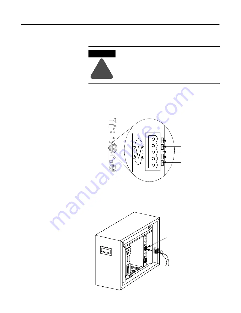
Connecting the Scanner to the DeviceNet Network
To connect to the DeviceNet network:
1.
Connect the DeviceNet drop line to the linear plug provided with
the scanner. Match the wire insulation colors to the colors shown
on the label.
2.
Locate the DeviceNet port connector for Channel 1 on the front of
the module.
3.
Insert the linear plug into the five-pin header for Channel 1.
ATTENTION
!
Do not wire your module with power applied to
your network. You may short circuit your network or
disrupt communication.
MODULE
STATUS
RESET
CHANNEL 1
NETWORK
STATUS
NODE/
ERROR CODE
Device
Net
CHANNEL 2
Device
Net
NETWORK
STATUS
NODE/
ERROR CODE
Front of
Scanner
Module
Module label shows
wiring color scheme
RED
WHITE
BARE
BLUE
BLACK
Dedicated DeviceNet
Drop Line
Channel 1 Port
Connector
Содержание DEVICENET 1771-SDN
Страница 1: ...PLC 5 DeviceNet Scanner Module 1771 SDN User Manual...
Страница 4: ......
Страница 12: ...Publication 1771 6 5 132 June 2000 P 8 About This User Manual...
Страница 16: ...Publication 1771 6 5 132 June 2000 Table of Contents iv...
Страница 28: ...Publication 1771 6 5 132 June 2000 1 12 Before You Begin...
Страница 38: ...Publication 1771 6 5 132 June 2000 2 10 Planning Your Configuration and Data Mapping Your Devices...
Страница 52: ...Publication 1771 6 5 132 June 2000 3 14 Hardware Setup...
Страница 70: ...Publication 1771 6 5 132 June 2000 4 18 Configuring the DeviceNet Network...
Страница 94: ...Publication 1771 6 5 132 June 2000 5 24 Communicating with DeviceNet from Another Network...
Страница 118: ...Publication 1771 6 5 132 June 2000 B 4 Installing and Configuring the ControlNet Communications Driver...
Страница 122: ...Publication 1771 6 5 132 June 2000 C 4 Installing and Configuring the DH Communications Driver...
Страница 132: ...Publication 1771 6 5 132 June 2000 D 10 Data Map Example...
Страница 137: ......
Страница 139: ...PLC 5 DeviceNet Scanner Module User Manual...


