Publication 1771-6.5.132 - June 2000
3-6
Hardware Setup
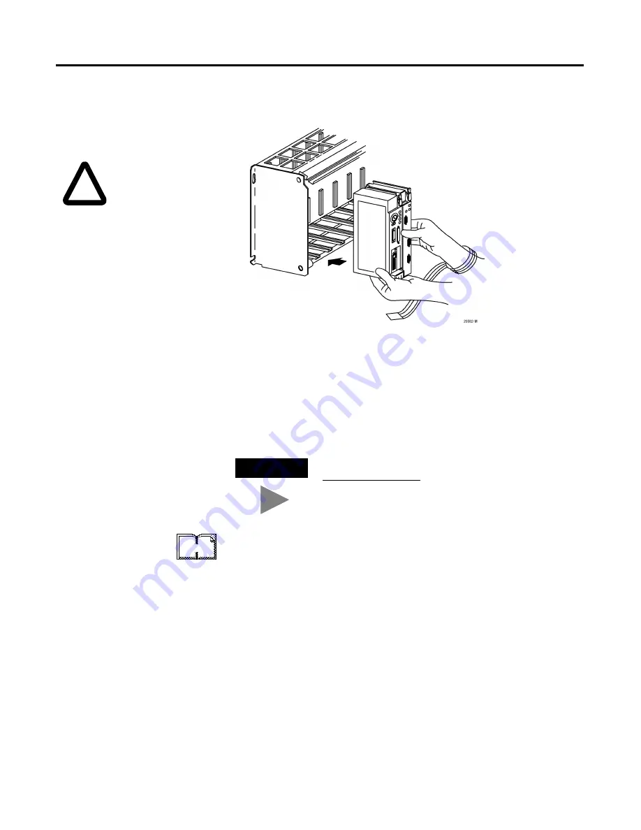
3.
Insert the interface module/processor combination in the left-most
slot of the 1771 I/O chassis.
4.
Assign an IP address to the interface module.
5.
Configure channel 3A for Ethernet communication.
You can configure the communication channel using BOOTP
software or your PLC-5 programming software. See Appendix A for
information on configuring the communication channel using
RSLogix 5
programming software.
For more information, see the PLC-5 Ethernet Interface Module User
Manual, publication 1785-6.5.19.
Be sure power to the
1771 I/O chassis is OFF.
!
TIP
Rockwell Automation offers a BOOTP tool on
http://www.ab.com
More
Содержание DEVICENET 1771-SDN
Страница 1: ...PLC 5 DeviceNet Scanner Module 1771 SDN User Manual...
Страница 4: ......
Страница 12: ...Publication 1771 6 5 132 June 2000 P 8 About This User Manual...
Страница 16: ...Publication 1771 6 5 132 June 2000 Table of Contents iv...
Страница 28: ...Publication 1771 6 5 132 June 2000 1 12 Before You Begin...
Страница 38: ...Publication 1771 6 5 132 June 2000 2 10 Planning Your Configuration and Data Mapping Your Devices...
Страница 52: ...Publication 1771 6 5 132 June 2000 3 14 Hardware Setup...
Страница 70: ...Publication 1771 6 5 132 June 2000 4 18 Configuring the DeviceNet Network...
Страница 94: ...Publication 1771 6 5 132 June 2000 5 24 Communicating with DeviceNet from Another Network...
Страница 118: ...Publication 1771 6 5 132 June 2000 B 4 Installing and Configuring the ControlNet Communications Driver...
Страница 122: ...Publication 1771 6 5 132 June 2000 C 4 Installing and Configuring the DH Communications Driver...
Страница 132: ...Publication 1771 6 5 132 June 2000 D 10 Data Map Example...
Страница 137: ......
Страница 139: ...PLC 5 DeviceNet Scanner Module User Manual...


