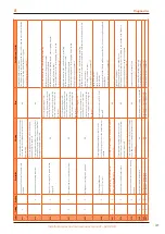
Robur GAHP-AR Скачать руководство пользователя страница 40

Diagnostics

40

8

Code

Cooling

Hea

ting

Description

W

arning

Err

or

Possible c

auses / C

hecks

616

X

X

Outlet w

at

er t

emper

atur

e sensor fault

(THM)

NA

Er

ror can be r

eset via S61, DDC or 

po

w

er off

Br

oken or shor

t in sensor wir

e

Possible bad c

onnec

tion a

t c

on

trol boar

d

If the pr

oblem persists

, c

on

tac

t A

T

617

X

X

Inlet w

at

er t

emper

atur

e sensor fault

(THR)

NA

Er

ror can be r

eset via S61, DDC or 

po

w

er off

Br

oken or shor

t in sensor wir

e

Possible bad c

onnec

tion a

t c

on

trol boar

d

If the pr

oblem persists

, c

on

tac

t A

T

618

X

X

Condenser outlet t

emper

atur

e sensor 

fault

y (

TCN)

NA

Er

ror can be r

eset via S61, DDC or 

po

w

er off

Br

oken or shor

t in sensor wir

e

Possible bad c

onnec

tion a

t c

on

trol boar

d

If the pr

oblem persists

, c

on

tac

t A

T

620

X

X

Condenser inlet t

emper

atur

e sensor fault

(TG

)

NA

Er

ror can be r

eset via S61, DDC or 

po

w

er off

Br

oken or shor

t in sensor wir

e

Possible bad c

onnec

tion a

t c

on

trol boar

d

If the pr

oblem persists

, c

on

tac

t A

T

628

X

X

Gas v

alv

e ener

giz

ed with ig

nition malfunc

-

tion c

ode (E 12) ac

tiv

e

NA

Er

ror can be r

eset via S61, DDC or 

po

w

er off

If the pr

oblem persists

, c

on

tac

t A

T

629

X

X

Ig

nition malfunc

tion

No v

oltage supplied t

o gas v

alv

e fr

om 

Fen

w

al af

ter 120 sec

onds fr

om call f

or 

flame b

y the S61 boar

d

W

ar

ning will aut

oma

tically r

eset if gas v

alv

e is 

po

w

er

ed within 10 minut

es fr

om call f

or flame 

or

, if af

ter 5 min of oper

ation the w

ar

ning is 

gener

at

ed

, then it will r

eset if ther

e is no longer 

call f

or oper

ation

Er

ror can be r

eset via S61, DDC or 

po

w

er off

Possible blocked flue passage

Bad or fault

y air pr

essur

e diff

er

en

tial swit

ch - possibly stuck closed or stuck open

Bad or fault

y pr

e-mix blo

w

er assy mot

or

Debr

is on blo

w

er wheel pr

ev

en

ting full air flo

w

Cr

acked or clogged air tubes c

onnec

ting blo

w

er assy t

o pr

essur

e diff

er

en

tial swit

ch

Possible loss of flame sensing af

ter 5 minut

es of oper

ation

Possible gas v

alv

e issue af

ter 5 minut

es of oper

ation

If the pr

oblem persists

, c

on

tac

t A

T

631

X

W

at

er t

emper

atur

e abo

ve oper

ational 

limits in hea

ting mode

FW v

er

. 3.026 or la

ter

W

ar

ning will r

eset aut

oma

tically when t

empe

-

ra

tur

e dr

op b

y 3,6 °F belo

w limit

NA

Ligh

t load c

onditions

Lo

w w

at

er flo

w

Oper

ation in c

onjunc

tion with 3r

d par

ty boilers in loop c

onfigur

ation tha

t allo

ws 

hott

er w

at

er t

o flo

w thr

ough units

If the pr

oblem persists

, c

on

tac

t A

T

632

X

W

at

er t

emper

atur

e belo

w oper

ational 

limits in c

ooling mode

FW v

er

. 3.026 or la

ter

W

ar

ning will r

eset aut

oma

tically when t

empe

-

ra

tur

e incr

eases b

y 3,6 °F abo

ve limit

NA

Ligh

t load c

onditions

Lo

w w

at

er flo

w

If the pr

oblem persists

, c

on

tac

t A

T

644

X

X

TA1 t

emper

atur

e sensor fault

y (wir

e is 

labeled T

CN)

NA

Er

ror can be r

eset via S61, DDC or 

po

w

er off

Br

oken or shor

t in sensor wir

e

Possible bad c

onnec

tion a

t c

on

trol boar

d

If the pr

oblem persists

, c

on

tac

t A

T

646

X

High hot w

at

er inlet t

emper

atur

e

W

ar

ning will r

eset aut

oma

tically when t

empe

-

ra

tur

e dr

ops b

y 9.0 °F belo

w limit

NA

Ligh

t load c

onditions

Lo

w w

at

er flo

w

Possible applica

tion or piping issues if w

or

king in c

onjunc

tion with 3r

d par

ty 

boilers allo

wing hott

er w

at

er t

o en

ter hea

t pump

If the pr

oblem persists

, c

on

tac

t A

T

647

X

Lo

w hot w

at

er inlet t

emper

atur

e

Reset is aut

oma

tic when the tr

igger

ing 

condition c

eases

, or 430 s af

ter the w

ar

ning w

as 

gener

at

ed

Reset is aut

oma

tic when the 

trigger

ing c

ondition c

eases

Building load c

onditions g

rea

ter than output of unit

Possible c

old w

at

er star

ting c

onditions

If the pr

oblem persists

, c

on

tac

t A

T

648

X

Hot w

at

er diff

er

en

tial t

oo high

Reset is aut

oma

tic when the tr

igger

ing 

condition c

eases

, or 20 minut

es af

ter the c

ode 

is gener

at

ed

Reset is aut

oma

tic when the 

trigger

ing c

ondition c

eases

Lo

w w

at

er flo

w

Failing t

emper

atur

e sensor or sensor not mak

ing good c

on

tac

t

If the pr

oblem persists

, c

on

tac

t A

T

649

X

X

Auxiliar

y hea

ting boar

d not r

ec

og

niz

ed

Reset is aut

oma

tic when the tr

igger

ing c

ondi

-

tion c

eases

Reset is aut

oma

tic when the 

trigger

ing c

ondition c

eases

Bad cable c

onnec

tion bet

w

een boar

ds

Inc

or

rec

t c

on

trol boar

d par

amet

ers

If the pr

oblem persists

, c

on

tac

t A

T

Содержание GAHP-AR

Страница 1: ...GAHP AR air water reversible absorption heat pump gas powered Installation use and maintenance manual...

Страница 2: ...f this Installation use and maintenance manual other than for personal consultation must be previously authorised by Robur Corporation The rights of those who have legitimately filed the registered tr...

Страница 3: ...quality p 22 3 8 System filling p 23 3 9 Fuel gas supply p 23 3 10 Combustion products exhaust p 23 3 11 Flue gas condensate discharge p 24 3 12 Defrosting water drainage p 25 4 Electrical installer p...

Страница 4: ...Gas Utilization Efficiency efficiency index of gas heat pumps equal to the ratio between the thermal energy pro duced and the energy of the fuel used relative to NCV net calo rific value First start...

Страница 5: ...solution is contained in the sealed circuit The solution is harmful for health if it is in gested inhaled or comes in contact with the skin In the event of coolant leak keep away and disconnect the po...

Страница 6: ...tem Other applicable provisions and standards The design installation operation and maintenance of the sys tems shall be carried out in compliance with current applicable regulations depending on the...

Страница 7: ...hiller and the heat taken away from the cooled environment via the hydraulic cir cuit is dissipated towards the outside via the air cooled finned coil 1 1 1 1 Heating in winter The appliance uses the...

Страница 8: ...nti vibration joints 10 1 2 48 1 2 38 3 8 A 60 7 8 50 1 2 50 3 4 20 7 8 33 1 2 4 27 3 8 A 5 7 8 Figure 1 2 Service plate with plumbing and gas connections A Water outlet connection 1 1 4 F B Water inl...

Страница 9: ...Internal components front view 1 Tapping point for flue analisys 2 Combustion air intake 3 Combustion blower 4 Gas valve 5 Electrical panel 6 Oil pump 7 Water inlet connection 1 1 4 F 8 Water outlet...

Страница 10: ...Features and technical data 10 1 Figure 1 4 Internal components left side view 1 Generator fins temperature probe 2 80mm flue gas exhaust 3 Flame sensor ignition electrodes 1 2 3...

Страница 11: ...al GAHP AR 11 1 Figure 1 5 Internal components right side view 1 Safety valve 2 Return temperature probe 3 Defrosting valve 4 TG generator temperature probe 5 Limit thermostat 6 Outlet temperature pro...

Страница 12: ...rvicing the controls Wiring errors can cause improper and dan gerous operation Figure 1 6 GAHP AR wiring diagram 1 5 ELECTRONIC BOARDS The unit s electrical board contains Electronic board S61 Figure...

Страница 13: ...robe input SPI Not used P8 GND L H CAN bus connector J1 CAN bus Jumper A1 A2 Connections for actuator s limit switches TF Not used TL Generator limit thermostat input FL Water flow switch input FS5 Bo...

Страница 14: ...timer switch contactor fitted with voltage free NO contact This system only provides elementary control on off with fixed setpoint temperature hence without the im portant functions of system 1 It is...

Страница 15: ...inch WC 0 048 Dimensions width 33 1 2 depth 48 1 2 height 50 3 4 6 Weight in operation pounds 838 shipping pounds 883 General information Cooling fluid ammonia R717 pounds 15 7 water H2O pounds 22 0 1...

Страница 16: ...20 6 86 F Outlet 104 F Outlet 122 F Outlet Water flow GPM Pressure drop feet of head Cooling Table 1 3 Cooling mode pressure drop Water flow rate Outlet water temperature GPM 37 4 F 44 6 F 50 0 F ft...

Страница 17: ...to operate under partial load conditions and in non stationary operation Table 1 5 GAHP AR cooling capacity kBtu hr External air temperature dry bulb F Hot water outlet temperature F 37 4 44 6 50 0 T...

Страница 18: ...g water drainage In winter it is normal for frost to form on the finned coil and for the appliance to perform defrosting cy cles To prevent overflowing and damage provide for a drain age system Acoust...

Страница 19: ...necessary provide a maintenance walkway around the ap pliance Although approved for installation on a combustible base the appliance must not be installed directly on the roof surface Use base support...

Страница 20: ...ydraulic system into two parts primary and secondary circuit uncoupled by a hydraulic separator or possibly by a tank that also acts as inertial tank buffer Water flow rate The GAHP AR unit works with...

Страница 21: ...ng 1 safety valve 1 expansion tank of the individual unit The appliance is not equipped with an expansion tank therefore it is necessary to install a suitable expansion tank sized in relation to the m...

Страница 22: ...1 26 1 47 2 79 Ethylene glycol correction factors Percent ethylene glycol 10 15 20 25 30 35 40 Approximate freezing point in F 25 21 17 11 5 0 10 Capacity factor multiplier 1 0 98 0 96 0 95 0 93 0 92...

Страница 23: ...ction between the appliance and the gas piping An approved union should be installed in the gas line near the unit and downstream of any external shut off valve that may be required by local codes Fig...

Страница 24: ...ossible flue If necessary the appliance may be connected to a flue To size the flue refer to following Table 3 3 p 24 The flue must be designed sized tested and constructed by a skilled firm with mate...

Страница 25: ...responsible for any damages caused by the failure of the grounding system Installation must comply with applicable regulations in force based on the installation Country and site in mat ters of safet...

Страница 26: ...accidental pulling Figure 4 1 Wiring for a single unit with pump absorbed current less than 4 A 1 General switch 2 Use a 15 A time lag fuse on L wire 3 Ground pin 4 Ground cable has to be connected by...

Страница 27: ...ly or OPEN Detail B if the node is intermediate two connected CAN bus cable sections 4 Connect the DDC to the CAN bus cable according to the in structions of the following Paragraphs and DDC Manual Fi...

Страница 28: ...N bus cable section only or OPEN Detail B if the node is intermediate two connected CAN bus cable sections Figure 4 5 Connection of the CAN bus cable to the control panel DDC Direct Digital Control GN...

Страница 29: ...ltage ter minal block located in the electrical control panel as shown in Figure 4 1 p 26 the minimum circuit ampacity for the unit must be increased above that listed in the technical data Table 1 1...

Страница 30: ...with its design following the instructions supplied by the manufacturer and respecting current regulation The project must have been carried out by a skilled professional Check personally that all of...

Страница 31: ...itable panel mov ing it to the ON position Power up the DDC if provided Switch on the appliance by means of the provided control device DDC or external request Adjust the gas pressure to the appliance...

Страница 32: ...r adjustment 7 Open control switch and make sure that the appliance is off 8 Remove manometer and pressure tap Replace plug in gas valve 9 Turn on the appliance by closing control switch Check all gas...

Страница 33: ...ve fuse holder The maximum current carrying capacity of the N O Contact is 4 A Paragraph 4 5 p 29 Isolation relay An isolation relay must be used to separate the appli ance s transformer from any addi...

Страница 34: ...rder e g display 2 _20 param eter 20 in menu 2 7 Turn the knob clockwise to scroll down the other param eters in the menu the codes will be displayed in order e g display 2 _20 2 _21 2 _25 parameters...

Страница 35: ...the pre existing value press the knob again otherwise go to step 3 3 Turn the knob to modify the value increasing or decreas ing it and press it to set the new value 4 Exit menu 3 and from the menu l...

Страница 36: ...also be done by the user Any operation on internal components may exclusively be performed by the AT Before performing any operation switch off the appli ance by means of the control device DDC or ex...

Страница 37: ...er down and out to remove it from gen erator housing Be careful not to distort or damage the burner tube or the flame sensor ignition electrodes assemblies in the generator housing 7 Position the burn...

Страница 38: ...ke sure that the main power supply switch GS fitted by the electrical installation technician on a suitable panel Figure 4 1 p 26 is in the ON position Check that the gas supply valve is open Check th...

Страница 39: ...unit and probe 606 X X Low ambient temperature Warning will automatically reset after condition is corrected NA Check location of the unit and probe 607 X X High condenser inlet temperature Warning wi...

Страница 40: ...the problem persists contact AT 631 X Water temperature above operational limits in heating mode FW ver 3 026 or later Warning will reset automatically when tempe rature drop by 3 6 F below limit NA L...

Страница 41: ...ct AT 656 X X Ambiguous reversing valve position NA Reset by powering unit off then on An automatic reset can occur if after a new transition from one mode to the other the micro switch status emerges...

Страница 42: ...fuse Bad connection between transformer and low voltage connection to board Faulty transformer If the problem persists contact AT 685 X X Incorrect unit types NA Error can be reset via power off New...

Страница 43: ......

Страница 44: ...ndly energy efficiency products through the commitment and caring of its employees and partners Revision H Code D LBR364 19 MCL SVI 006 11 06 2020 Robur Corporation advanced technologies for air condi...

Отзывы: