


Electrical installer
Installation, use and maintenance manual – GAHP-AR
29
4
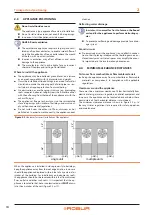
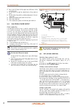
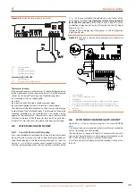
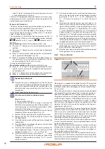
Figure 4.6
External operation requests connection
SCH
Electronic board
R
Common
W
Heating request terminal
Y
Cooling request terminal
Components NOT SUPPLIED
CS
External request
W/Y
Hot/cold switch (summer/winter)
Thermostat location
If the external request is a thermostat, it should be located on an
inside wall about 54 inches above the floor. It should be located
so that it will no be affected by any of the following items:
▶
discharge air from a supply grille
▶
drafts
▶
direct sunlight through a window or glass door
▶
electrical appliances such as television, radio or lamps
The thermostat should be located so that it senses the average
temperature of the climatized space. The thermostat should be
mounted according to the manufacturer’s instructions (pack-
aged with the thermostat). Thermostats using a mercury bulb
switch must be level. If the thermostat has a built-in heating an-
ticipator, this must be set as required by the heating unit load.
4.5
WATER CIRCULATION PUMP
4.5.1
Constant flow circulation pump
It must be mandatorily controlled from the S61 electronic board.
If power for the water pump is taken from the high voltage ter-
minal block located in the electrical control panel, as shown in
Figure 4.1
p. 26, the minimum circuit ampacity for the unit
must be increased above that listed in the technical data (Table
1.1
p. 14) to accommodate the additional current draw of the
water pump installed.
The maximum current carrying capac-
ity of the N.O. contact is 4 A
. If the current is above 4 A, use
an additional relay controlled by N.O. contact on the S61 board
(Figure 4.7
p. 29).
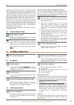
Jumper J10 must be opened if the pump is > 700 W, otherwise
it must be closed.
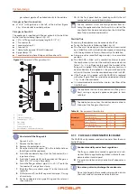
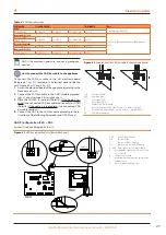
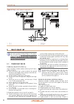
Figure 4.7
Wiring for a single unit with pump absorbed current more
than 4 A
1
General switch
2
Use a 15 A time lag fuse on L wire
3
Ground pin
4
Ground cable has to be connected by a suitable eyelet to the ground
pin into the electrical panel, and fixed to it by the proper preset nut.
5
L, N wiring to the terminal board must be done respecting the correct
polarity
6
Jumper open
6
1
2
3
4
5
PUMP
TER
R2
L
F
N
GS
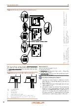
4.6
WITH MORE THAN ONE GAHP-AR UNIT
Figure 4.8
p. 30 shows typical wiring for 2 or more GAHP-AR
units.
It is always necessary to provide a safety transformer (secondary
SELV) and a respective control relay.
The transformer is required to feed N.O. contacts with low volt-
age current, for safety reasons: when doing maintenance and a
unit is shut off, these contacts could still remain fed.
In this case, no matter if pump current absorption is more or less
than 4 A.


