


System design
24
3
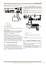
gas exhaust pipe to a flue linked directly to the outside.
Flue gas exhaust connection
▶
Ø 3-1/8" (with gasket), on the left, at the bottom (Figure
3.5
p. 24) and outlet in vertical position.
Flue gas exhaust kit
The appliance is supplied with flue gas exhaust kit, to be fitted
by the installer, including (Figure 3.5
p. 24):
▶
1 Ø 3-1/8" flue gas exhaust pipe, length 29-1/2" (C)
▶
1 T connector (E)
▶
1 condensate trap (F)
▶
1 terminal (A)
▶
1 clamp for fixing pipe (B) to left side panel
▶
4 pipe clamps (D)
▶
1 condensate drain hose fitting and silicone hose (G)
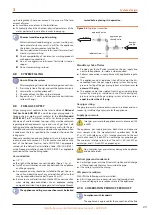
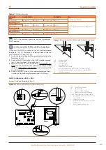
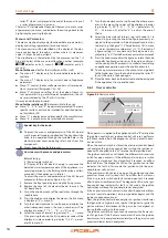
Figure 3.5
Components of flue gas exhaust kit
A
Terminal
B
Clamp for fixing pipe
C
Exhaust pipe L = 29-1/2"
D
Pipe clamp
E
T connector
F
Condensate drip pan
G
Hose a condensate drain pipe
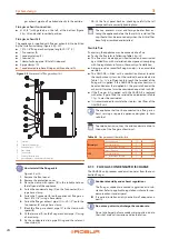
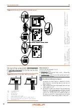
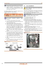
How to install the flue gas kit
Figure 3.5
1.
Remove the front panel.
2.
Remove the protection cover.
3.
Place the clamp with spacer (B) in the suitable hole on
the left panel of the appliance.
4.
Fasten the condensate trap (F) on the T connector (E) us-
ing a hose clamp.
5.
Fasten the T connector (E) on the appliance's flue gas ex-
haust (Ø 3-1/8") using a hose clamp.
6.
Fasten the flue gas exhaust pipe (C) (L = 29-1/2") onto the
T connector (E) using a hose clamp.
7.
Block the flue gas exhaust pipe (C) in the clamp with
spacer (B).
8.
Fit the terminal (A) on the flue gas exhaust pipe (C) using
a hose clamp.
9.
Fix the condensate drain pipe fitting and the relevant
silicon tube (G).
10.
Fit the front panel back on, checking carefully that all
components are correctly fixed in place.
The cap prevents water and foreign bodies from en-
tering the appliance before the fumes kit is installed. The
cap should thus be removed only when the kit itself has
been fully assembled and installed.
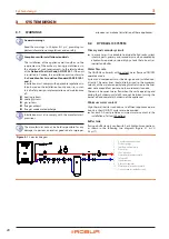
Possible flue
If necessary, the appliance may be connected to a flue.
▶
To size the flue refer to following Table 3.3
▶
The flue must be designed, sized, tested and constructed
by a skilled firm, with materials and components complying
with the regulations in force in the country of installation.
▶
Always provide a socket for flue gas analysis, in an accessible
position.
▶
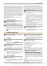
The GAHP-AR is fitted with a combustion blower towards
the combustion system, but the residual head indicated in
Table 1.1
p. 14 is sufficient only to reach the terminal of the
flue gas kit supplied. If the GAHP-AR flue gas exhaust must
be extended over the supplied kit, the pressure head at the
exhaust kit terminal must be considered equal to 0 inch WC.
▶
If the flue gas kit supplied with the GAHP-AR is replaced
with other types of flue, the residual head indicated in Table
p. 14 must be considered.
▶
It is recommended to insulate the stainless steel flues of the
GAHP-AR unit.
The appliance shall not be connected to a flue gas ex-
haust serving a separate appliance designed to burn
solid fuel.
To avoid corrosion, convey the acid condensate drain to
the base of the flue gas exhaust duct.
Table 3.3
Flue gas exhaust characteristics
Natural gas
Fumes flow rate
SCF
1750
Flue temperature
°F
293
CO
2
percentage in fumes
%
9.2
LPG
Fumes flow rate
SCF
1522
Flue temperature
°F
284
CO
2
percentage in fumes
%
11.3
3.11
FLUE GAS CONDENSATE DISCHARGE
The GAHP-AR unit produces condensation water from the com-
bustion flue gas.
Condensate acidity and exhaust regulations
The flue gas condensate contains aggressive acid sub-
stances. Refer to applicable regulations in force for con-
densate exhaust and disposal.
If required, install an acidity neutraliser of adequate ca-
pacity.
Do not use gutters to discharge the condensate.
Do not discharge the fume condensate in gutters, due to
the risk of materials corrosion and ice formation.


