


System design
Installation, use and maintenance manual – GAHP-AR
21
3
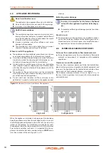
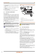
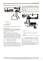
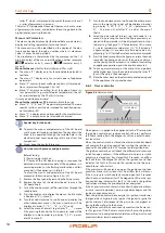
Figure 3.2
4-pipe tank diagram
1
Anti-vibration connection
2
Pressure gauge
3
Inlet flow control device
4
Water filter
5
Shut-off valves
6
Water pump (primary circuit)
7
Safety valve
8
Expansion tank
9
4-connection inertial buffer tank
10 Water pump (secondary circuit)
GAS
1
2
3
4
5
7
8
10
9
6
P
P
3.3
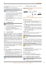
HYDRAULIC CONNECTIONS
Plumbing fittings
on the right, at the bottom, connection plate (Figure 1.2
▶
A (= out) 1 1/4" F - WATER OUTLET (m = outlet to the system)
▶
B (= in) 1 1/4" F - WATER INLET (r = return from the system)
Hydraulic pipes, materials and features
▶
Use pipes for heating/cooling installations, protected from
weathering, insulated for thermal losses, with vapour barrier
to prevent condensation.
Pipe cleaning
Before connecting the appliance,accurately wash the
water and gas piping and any other system component,
removing any residue.
Minimum components of primary plumbing circuit
Always provide, near the appliance:
▶
on water piping, both output and input
2 antivibration joints on water fittings
2 pressure gauges
2 isolation ball valves
▶
on the inlet water piping
1 separator filter
1 inlet flow control device, if the circulation pump is with
constant flow
1 water circulation pump, towards the appliance
▶
on the output water piping
1 safety valve
1 expansion tank of the individual unit
The appliance is not equipped with an expansion tank:
therefore it is necessary to install a suitable expansion
tank, sized in relation to the maximum heat excursion
and maximum operating pressure of the system's water.
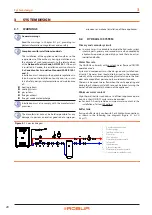
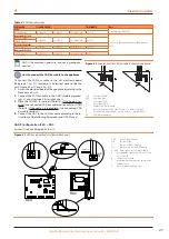
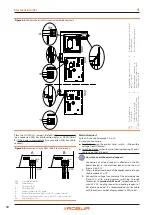
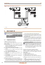
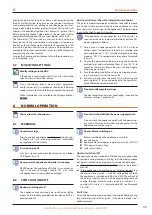
Figure 3.3
Hydraulic plan
The inlet flow control device must only be
used when the primary circuit circu-
lation pump is constant flow type
A
Gas connection
1
Anti-vibration connection
2
Pressure gauge
3
Inlet flow control device
4
Water filter
5
Shut-off valves
6
Water pump (primary circuit)
7
Safety valve
8
Expansion tank
9
Hydraulic separator / inertial tank with
4 fittings
10 Water pump (secondary circuit)
3.4
WATER CIRCULATION PUMP
The circulation pump (flow and head) must be selected and
installed based on pressure losses of plumbing/primary circuit
( comp exchange ter appliance).
For the appliance pressure losses refer to Table 1.1
p. 14 and to
Paragraph 1.7.1
Constant flow circulation pump
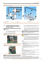
The primary circulating pump must be obligatorily controlled
by the appliance's electronic board (S61) (see Paragraph
p. 12).
3.5
ANTIFREEZE FUNCTION
Antifreeze self-protection
The appliance is equipped with an active antifreeze self-protec-
tion system to prevent freezing during wintertime, therefore in
heating mode. The antifreeze function (activated by default) au-
tomatically starts the primary circulation pump and, if required,
the burner too, when the outside temperature approaches 32 °F.


