


Features and technical data
12
1
1.4
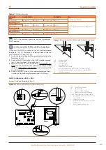
ELECTRICAL WIRING DIAGRAM
If any of the original wire as supplied with the unit must
be replaced, it must be replaced with thermoplastic 221
°F wire, except ground, high temperature and pressure
switch wires, which must be 392 °F or equivalent.
Igniter and flame sensor wire have to be replaced with
Robur spare parts.
Label all wires prior to disconnection when servicing
the controls. Wiring errors can cause improper and dan-
gerous operation.
Figure 1.6
GAHP-AR wiring diagram
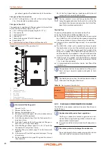
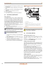
1.5
ELECTRONIC BOARDS
The unit's electrical board contains:
▶
Electronic board S61
(Figure 1.7
p. 13), with micropro-
cessor, it controls the appliance and displays data, messages
and operative codes. The appliance is monitored and pro-
grammed by interacting with the display and the knob.
▶
Satellite AR11 electronic board
(Figure 1.8
p. 14), inter-
connected to the S61 board and located next to it, used to
control the cycle switching valve and to control defrosting
operations of the GAHP-AR unit.


