4 Electrical installer
Installation, Use and Maintenance Manual – GAHP-A
29
4�5 WATER CIRCULATION PUMP
4�5�1 Option (1) CONSTANT FLOW circulating pump
It must be mandatorily controlled from the S61 electronic board.
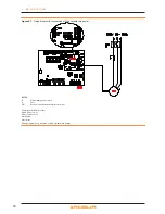
The diagram in Figure 4.6 p. 29 is for pumps < 700 W. For
pumps > 700 W it is required to add a control relay and arrange
Jumper J10 OPEN.
How to connect the CONSTANT FLOW circulating
pump
Access the Electrical Board of the appliance according
to the Procedure 4.2 p. 25
1. connect board S61, to terminals 3-4 of terminal
board (MA);
2. Jumper J10 CLOSED.
Figure 4�6 – Electrical wiring diagram
Example of pump/appliance electrical connection with 230 Vac pump (with absorbed power of < 700 W), controlled directly by the appliance.
4�5�2 Option (2) VARIABLE FLOW circulating pump
It must be mandatorily controlled from the Mod10 electronic
board (built into the S61).
How to connect the VARIABLE FLOW circulating
pump
The Wilo Stratos Para pump is already standard supplied
with the power supply cable and signal cable, both
1.5m long.
For longer distances, use respectively cable FG7
3Gx1.5mm² m and shielded cable 2x0.75 mm² suitable
for 0-10V signal.
To connect the Wilo Stratos Para pump (Figure
4.7 p. 30 J 45 or 4.8 p. 31 J 46)
1. Connect the brown wire of the pump to terminal "-"
HPMP of the Mod10 board, and the white wire of the
pump to terminal "+" HPMP of the Mod10 board.
2. Isolate the black wire and the blue one.
3.
Protect the pump's supply line with a double
pole switch with 2 A delayed fuse (Detail IP, Fig-
ure 4.7 p. 30 J 45), or connect it directly to the
terminals inside the appliance's Electrical Board (De-
tail MA, Figure 4.8 p. 31 J 46).
LEGEND
SCH
circuit board
J10
closed jumper
N.O. CONTACT
N.O voltage free contacts
MA
unit terminal block
L
phase
N
neutral
Components NOT SUPPLIED
PM
water pump <700W


