background image


1  Features and technical data 

Installation, Use and Maintenance Manual – GAHP-A 

15

Figure 1�10 – Mod10 controller

Mod10 controller

Figure 1�11 – W10 electronic controller

1�6  OPERATION MODE

ON/OFF or modulating operation
The GAHP unit may work in two modes:


 mode  (1)  ON/OFF, i.e. On (at full power) or Off, with circulat-

ing pump at constant or variable flow;


 mode  (2)  MODULATING, i.e. at variable load from 50% to 

100% of power, with circulating pump at variable flow.

LEGEND

HFLOW 

  Not used

CFLOW 

  Condensation water sensor control

J51 

  SPI connector

HPMP 

  Primary circuit hot water pump control 

output (0-10 V)

CPMP 

 Low consumption fan control output 

(0-10V)

NC1-C1 

  Status indication of locking warnig/error

CN5 

  Blower control

J82 

  W10 auxiliary controller connector

J83 

  W10 cable shielding connection W10

CN1 

  Inputs 0-10V (not used)

LEGEND

FS1 

 Defrosting valve contact

JP1 

 Communication with S61/Mod10

Содержание GAHP-A

Страница 1: ...Installation Use and Maintenance Manual GAHP A powered by gas and renewable energies Air Water gas absorption heat pump ...

Страница 2: ...of this Manual other than for personal referencing must be previously authorised by Robur S p A The rights of those who have legitimately filed the registered trademarks contained within this publication are not affected With the aim of continuously improving the quality of its products Robur S p A reserves the right to modify the data and contents of this Manual without prior notice ...

Страница 3: ...on pump 21 3 5 Anti icing function 21 3 6 Anti icing liquid 21 3 7 System water quality 22 3 8 Installation filling 22 3 9 Fuel gas supply 22 3 10 Combustion products exhaust 23 3 11 Flue gas condensate discharge 24 3 12 Defrosting water drainage 24 4 ELECTRICAL INSTALLER 24 4 1 Warnings 24 4 2 Electrical systems 25 4 3 Electrical power supply 26 4 4 Set up and control 27 4 5 Water circulation pum...

Страница 4: ...ces Robur Box optional interface devices complementary to DDC which may be used to broaden its func tions heating cooling DHW production service demands and control of system components such as third party generators adjustment valves circulating pumps probes Heat generator equipment e g boiler heat pump etc pro ducing heating and or DHW GUE Gas Utilization Efficiency efficiency index of gas heat ...

Страница 5: ...ion The GAHP unit uses the ammonia water absorption cycle The water ammonia solution is contained in the sealed circuit The solution is harmful for health if it is ingested inhaled or comes in contact with the skin In the event of coolant leak keep away and discon nect the power and gas supply only if it is possible to do so with no danger Request assistance from the TAC Electrocution hazard Disco...

Страница 6: ...lation operation and maintenance of the sys tems shall be carried out in compliance with current applicable regulations depending on the Country and location and in accordance with the manufacturer s instructions In particular regulations regarding the following shall be complied with Gas systems and equipment Electrical systems and equipment Heating and air conditioning systems and heat pumps Env...

Страница 7: ...essor LCD display and knob Mod10 additional electronic board integrated in S61 auxiliary W10 electronic board installation water flowmeter generator limit thermostat with manual reset flue gas temperature thermostat with manual reset generator fin temperature sensor sealed circuit safety relief valve by pass valve between high and low pressure circuits ionisation flame controller gas solenoid valv...

Страница 8: ...1 Features and technical data 8 Figure 1 2 Size Standard ventilation Figure 1 3 Dimensions low consumption silenced fan ...

Страница 9: ...gure 1 4 Internal components front view 1 2 4 5 6 7 3 10 12 11 8 9 LEGEND 1 Fan S1 version 2 Flue gas tapping point 3 Gas valve 4 Combustion air inlet 5 Blower 6 Ignition transformer 7 Tmix Probe 8 Oil pump 9 Water return fitting G 1 F 10 Water inlet connection G 1 F 11 Gas connection 12 TA Probe ...

Страница 10: ...a 10 Figure 1 5 Internal components left side view LEGEND 1 Flue gas thermostat reset 2 Flue gas thermostat sensor 3 Ø 80mm flue gas drain 4 Generator fin temperature sensor 5 Switch on and detection electrodes 6 Condensate sensor ...

Страница 11: ...e and Maintenance Manual GAHP A 11 Figure 1 6 Internal components right side view LEGEND 1 TG Probe 2 Safety valve 3 Delivery pipe flowmeter 4 Delivery temperature probe 5 Limit thermostat 6 Defrosting valve 7 Return temperature probe 8 Teva Probe ...

Страница 12: ... indicator lamp GV Gas solenoid valve TC Manual fumes thermostat TL Generator limit thermostat FM Flowmeter CWS Condensation water sensor VD Defrosting valve FAN Fan CF Filter capacitor FS Condensate hose heating element THRC Hot water return temperature sensor THMC Hot water delivery temperature sensor TMIX Combustion air temperature sensor TA Ambient air temperature sensor TG Generator temperatu...

Страница 13: ...ry temperature sensor TMIX Combustion air temperature sensor TA Ambient air temperature sensor TG Generator temperature sensor TF Fumes temperature sensor or genera tor fin sensor TEVA Evaporator outlet temperature sensor TK Condensate discharge heating element thermostat MA Terminal block REED Hydraulic pump rotation sensor 1 5 ELECTRONIC BOARDS Electronic boards S61 Mod10 The unit s electrical b...

Страница 14: ... Board connector W10 on Mod10 JP10 6 pole flame control unit connector JP12 Flue gas probe input or generator fin probe JTAG Connector for board programming S61 MAIN 230V L N Board power supply S61 230 Vac CONTACT Normally open pump contact P7 R W Y O Enable input P8 GND L H Connector CAN BUS PUMP 230V L N Oil hydraulic pump power supply output SPI Communication port with board Mod10 SRT1 Oil hydr...

Страница 15: ...able flow mode 2 MODULATING i e at variable load from 50 to 100 of power with circulating pump at variable flow LEGEND HFLOW Not used CFLOW Condensation water sensor control J51 SPI connector HPMP Primary circuit hot water pump control output 0 10 V CPMP Low consumption fan control output 0 10V NC1 C1 Status indication of locking warnig error CN5 Blower control J82 W10 auxiliary controller connect...

Страница 16: ...nce may also be controlled via generic enable de vices e g thermostats clocks buttons contactors fitted with voltage free NO contact This system only provides elementary control on off with fixed set point temperature hence without the important functions of systems 1 and 2 It is advisable to limit its possible use only to simple applications and with a sin gle appliance For connection of the sele...

Страница 17: ...Diameter mm 80 Residual head Pa 80 Dimensions width mm 848 6 depth mm 1258 height mm 1281 6 1537 6 Weight In operation kg 390 400 Required air flow m3 h 11000 Fan residual head Pa 40 GENERAL INFORMATION INSTALLATION MODE B23P B33 B53P REFRIGERANT FLUID AMMONIA R717 kg 7 WATER H2O kg 10 MAXIMUM PRESSURE OFTHE REFRIGERANT CIRCUIT bar 32 Note 1 As per standard EN12309 2 2 For flows other than nominal...

Страница 18: ...he site ensure there is no transport damage on packing metal panels or finned coil After removing the packing materials ensure the ap pliance is intact and complete Packing Only remove the packing after placing the appliance on site Do not leave parts of the packing within the reach of children plastic polystyrene nails since they are potentially dangerous Weight The crane and lifting equipment mu...

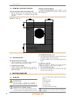
Страница 19: ...or on a roof compatibly with its dimensions and weight It must be installed outside buildings in an area of natural air circulation outside the dripping path of drainpipes or simi lar It does not require protection from weathering No obstruction or overhanging structure e g protruding roofs canopies balconies ledges trees shall interfere either with the air flowing from the top of the appliance or...

Страница 20: ...ation on terrace or roof The structure of the building must support the total weight of the appliance and the supporting base If necessary provide a maintenance walkway around the ap pliance Anti vibration mountings Although the appliance s vibrations are minimal resonance phenomena might occur in roof or terrace installations Use anti vibration mountings Also provide anti vibration connections be...

Страница 21: ...ump is con stant flow 1 WATER CIRCULATION PUMP towards the appliance on the output water piping m 1 SAFETY VALVE 3 bar 1 EXPANSION TANK of the individual unit Figure 3 1 Hydraulic plan 3 4 WATER CIRCULATION PUMP The circulation pump flow and head must be selected and installed based on pressure losses of plumbing primary circuit piping components exchange terminals appliance For the appliance s pr...

Страница 22: ...mg l 1 Langelier s index 0 0 4 HARMFUL SUBSTANCES Free chlorine mg l 0 2 3 Fluorides mg l 1 Sulphides ABSENT 1 with aluminium or light alloys radiators pH must also be low er than 8 in compliance with applicable rules 2 value referred to the maximum water temperature of 80 C 3 in compliance with applicable rules System water features Free chlorine or water hardness may damage the appliance Adhere ...

Страница 23: ...pliant gas pressure Table 3 3 p 23 may damage the appliance and be hazardous Vertical pipes and condensate Vertical gas pipes must be fitted with siphon and discharge of the condensate that may form inside the pipe If necessary insulate the piping LPG pressure reducers With LPG the following must be installed a first stage pressure reducer close to the liquid gas tank a second stage pressure reduc...

Страница 24: ...disposal If required install an acidity neutraliser of adequate capacity Do not use gutters to discharge the condensate Do not discharge the fume condensate water in gutters due to the risk of materials corrosion and ice formation Flue gas condensate connection The fitting for flue gas condensate discharge is located on the left side of the appliance Figure 3 3 p 24 The distance L between the slee...

Страница 25: ...ged in the long run occasional black outs are tolerated To turn the appliance on and off exclusively use the suitably provided control device DDC CCP CCI or external request Control of water circulation pump The water circulation pump of the hydraulic primary circuit must mandatorily be controlled by the unit s electronic boards S61 Mod10 It is not admissible to start stop the circulating pump wit...

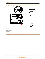
Страница 26: ...to the terminal TER in the electrical panel on the machine 3 Provide the earth lead in wire longer than live ones last to be torn in the event of accidental pulling Figure 4 2 Electrical wiring diagram Example of connection of appliance to 230 V 1 N 50 Hz electricity supply LEGEND A CAN BUS cable gland B signal cable gland 0 10 V pump Wilo Stratos Para C electronic boards S61 Mod10 W10 D terminal ...

Страница 27: ...OCVO008 ROBUR NETBUS H BLACK L WHITE GND BROWN 450 m Honeywell SDS 1620 In all cases the fourth conductor should not be used BELDEN 3086A H BLACK L WHITE GND BROWN 450 m TURCK type 530 DeviceNet Mid Cable TURCK type 5711 H BLUE L WHITE GND BLACK 450 m Honeywell SDS 2022 TURCK type 531 H BLACK L WHITE GND BROWN 200 m For lengths 200 m and max 4 nodes e g 1 DDC 3 GAHP a simple 3x0 75 mm shielded cab...

Страница 28: ...NO contact How to connect the external request Connection of external request is effected on the S61 board located in the Electrical Panel inside the unit Fig ure 4 5 p 28 1 Access the Electrical Board of the appliance accord ing to the Procedure 4 2 p 25 2 connect the voltage free contact of the external de vice through two conductor wires to terminals R and W respectively common 24 V AC and heat...

Страница 29: ... controlled from the Mod10 electronic board built into the S61 How to connect the VARIABLE FLOW circulating pump TheWilo Stratos Para pump is already standard supplied with the power supply cable and signal cable both 1 5m long For longer distances use respectively cable FG7 3Gx1 5mm m and shielded cable 2x0 75 mm suitable for 0 10V signal To connect the Wilo Stratos Para pump Figure 4 7 p 30 J 45...

Страница 30: ... Wilo variable rate pumps LEGEND IP Bipolar pump power switch F Fuse PM Hot water circulation pump primary circuit Pump signal 0 10V wire colours brown connect to ve white connect to ve black isolate blue isolate Wiring diagram for connection of Wilo variable rate pumps ...

Страница 31: ...ctly installed according to the manufactur er s instructions system installed in a workmanlike manner according to na tional and local regulations Abnormal or hazardous installation situations Should any abnormal or hazardous installation situations be found the TAC shall not perform First start up and the appliance shall not be commissioned These situations may be appliance installed inside a roo...

Страница 32: ...he re spective manuals If the appliance is controlled by external request e g ther mostat clock button with voltage free NO contact sys tem 3 see Paragraph 1 7 p 16 the appliance is switched on off by the ON OFF positions of the external control de vice After switching on with the control in normal operating condi tions the appliance starts stops automatically according to the user s thermal needs...

Страница 33: ... for functional data detected in real time the menu 1 display only for current values of appli ance parameters menu 2 control to execute flame control unit reset op erations reset errors Paragraph 6 6 p 34 menu 3 display and setting to set the value of some system parameters e g water set point temperature the values are initialised by the TAC at First Switch On It is accessed without password Men...

Страница 34: ...otating and pressing the knob 3 161 must be displayed procedure Para graph 6 4 p 32 2 Display the parameter value by pressing the knob the previously set value is displayed from 10 to 65 C to reconfirm the pre existing value press the knob again otherwise go to point 3 3 Turn the knob to modify the value increasing or de creasing it and press it to set the new value 4 Exit menu 3 and from the menu...

Страница 35: ... subject to heavy duty use for example in process plants or in other conditions of continuous operation maintenance operations must be more frequent 7 2 PRE EMPTIVE MAINTENANCE For pre emptive maintenance comply with the recommen dations in Table 7 1 p 35 Table 7 1 GUIDELINES FORTHE PREVENTIVE MAINTENANCE OPERATIONS Check of the unit GAHP A GAHP GS WS AY ACF GAHP AR Visually check of the general c...

Страница 36: ...2 3 7 p 22 and 3 6 p 21 Ensure the flue gas exhaust duct is not obstructed and that the condensate drain is clean After completing the above checks 1 Open the gas cock and ensure there are no leaks should gas smell be noticed close the gas cock again do not switch any electrical devices on and request intervention by Skilled Personnel 2 Power on with the main power supply switch GS Figure 4 2 p 26...

Страница 37: ...nu 2 parameter 21 If the code persists shows up again or in case of doubt contact theTAC 428 GAS SOLENOIDVALVE EXCITED DURING FLAME CONTROLLER ARREST NA Power off the appliance Contact authorisedTechnical Assistance 429 GAS SOLENOIDVALVEWITHOUT ELECTRICAL POWER Reset occurs automatically if the gas solenoid valve switches on again within 10 minutes with central flame control unit on Reset may be p...

Страница 38: ... Reset is automatic when the triggering condition ceases Contact authorisedTechnical Assistance 482 INVALID P1 PARAMETERS Reset is automatic when the triggering condition ceases Contact authorisedTechnical Assistance 484 FAULTYTRANSFORMER CONNEC TION OR 24V AC FUSES NA Contact authorisedTechnical Assistance 485 INCORRECT MODULETYPES NA Contact authorisedTechnical Assistance 486 FAULTY BOARD ROM NA...

Страница 39: ...ity with the following EC Directives 2006 42 EC Machinery Directive with subsequent amendments and integrations 2004 108 EC Electromagnetic Compatibility with subsequent amendments and integrations Tested and examined according to the following norms EN55014 1 EN55014 2 EN61000 3 2 EN61000 3 3 EN62233 2006 95 EC Low Voltage Directive with subsequent amendments and integrations Tested and examined ...

Страница 40: ...J Rated heat output Prated 36 4 kW Seasonal space heating energy efficiency η s 116 Tj 2 C Pdh 36 4 kW Tj 2 C PERd 119 Tj 7 C Pdh 23 3 kW Tj 7 C PERd 122 Tj 12 C Pdh 10 6 kW Tj 12 C PERd 116 Tj bivalent temperature Pdh kW Tj bivalent temperature PERd Annual energy consumption Q HE 151 GJ Table 8 COMMISSION DELEGATED REGULATION EU No 811 2013 Parameters shall be declared for average colder and warm...

Страница 41: ... flow rate outdoors __ 10000 m h Sound power level indoors outdoors L WA 80 dB For water or brine to water heat pumps Rated brine or water flow rate outdoor heat exchanger __ m h Additional information required by COMMISSION REGULATION EU No 813 2013 Table 2 Emissions of nitrogen oxides NO x 40 mg kWh For heat pump space heaters and heat pump combination heaters the rated heat output Prated is equ...

Страница 42: ...heat output Prated 36 4 kW Seasonal space heating energy efficiency η s 117 Tj 2 C Pdh 36 4 kW Tj 2 C PERd 120 Tj 7 C Pdh 23 3 kW Tj 7 C PERd 123 Tj 12 C Pdh 10 6 kW Tj 12 C PERd 118 Tj bivalent temperature Pdh kW Tj bivalent temperature PERd Annual energy consumption Q HE 150 GJ Table 8 COMMISSION DELEGATED REGULATION EU No 811 2013 Parameters shall be declared for average colder and warmer clima...

Страница 43: ... flow rate outdoors __ 10000 m h Sound power level indoors outdoors L WA 74 dB For water or brine to water heat pumps Rated brine or water flow rate outdoor heat exchanger __ m h Additional information required by COMMISSION REGULATION EU No 813 2013 Table 2 Emissions of nitrogen oxides NO x 40 mg kWh monovalent For heat pump space heaters and heat pump combination heaters the rated heat output Pr...

Страница 44: ... T 39 035 888111 F 39 035 884165 www robur it robur robur it Robur is dedicated to dynamic progression in research development and promotion of safe environmentally friendly energy efficiency products through the commitment and caring of its employees and partners Revision V Code D LBR548 15MCMSDC013 24 09 2015 ...

Отзывы: