


Rhein-Nadel Automation GmbH
12
VT-BA-ESR2000_EN-2019 / 05.08.2019 SJ
The controller display (membrane keypad)
On / Off
Pressing this button switches off all connected devices. The display shows "OFF".
The controller remains ready for operation.
Cursor up and cursor down
Use these buttons to scroll through the controller menu or set the parameters.
Enter
Press this button to acknowledge the parameters entered with the cursor.
Decimal point in the display
The decimal point is not blinking. You cannot make any entry.
The decimal point is blinking, an entry can be made.
4.2.
Starting-up the controller
To start up the controller, close the main disconnect switch. The main menu appears on the display showing the last
setpoint entered (feed rate of the bowl feeder or linear feeder).
KANAL l
KANAL 2
CODE
Alternatively, the following may appear on the display depending on the switching status of the device:
KANAL l
KANAL 2
CODE
External enabling signal has been activated but it is withdrawn from the device at the
moment. (medium priority)
KANAL l
KANAL 2
CODE
Device has been switched off by operating the top left button of the membrane keypad,
inhibiting all functions. (high priority)
KANAL l
KANAL 2
CODE
The accumulation monitoring sensor is operated, switching off the bowl feeder. (low
priority)
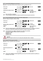
4.3.
Main menu / Setpoint entry and display
Display of setpoint or feed rate of the
bowl feeder
Alternatively: STOP, OFF or
ACCUMULATION (see above)
KANAL l
KANAL 2
CODE
No entry possible
Entry of the codes to change or
execute the required settings.
KANAL l
KANAL 2
CODE
Enter code.
Description of codes see
under 4.4.
Setpoint entry
(bowl feeder or linear feeder)
KANAL l
KANAL 2
CODE
Entry in %; return to
display mode for
saving
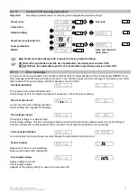
From these three basic screens of the main menu you can scroll in the main menu using the cursor buttons
(UP/DOWN). In each individual item of the main menu you can press ENTER to activate this item for setting or
changing. Upon pressing of the ENTER button the decimal point starts blinking. Now you can make changes using the
cursor buttons (UP/DOWN). Press ENTER again to acknowledge the entries made. The decimal point is no longer
blinking. Using the cursor buttons you can continue scrolling in the menu. Same procedure analogously applies to the
code menus described below.


