background image

Rhein-Nadel Automation GmbH


13  

VT-BA-ESR2000_EN-2019 / 05.08.2019 SJ 

 
All  the  following  display  screens  show  the  default  setting.  If  the  actual  display  on  the  controller  differs  the  default 
setting has been changed in individual codes to suit a specific application. 

4.4. 

Description of individual codes for controller programming. 


KANAL l
KANAL 2

CODE


Settings for the vibrating drive 

In this sub-menu you can set or limit the following functions: 
- Vibrating amplitude signal direction of external enabling input  
- External enabling  
- Soft start and stop delay 
- Output frequency 

KANAL l
KANAL 2

CODE


Sealing a setpoint 

In this sub-menu you can lock the setpoints (vibrating amplitude) of the main menu. It is no 
longer possible to change the setpoints for channel 1 in the main menu. This avoids 
accidental changes to performance parameters. You can only make any changes now 
through code C001. 

KANAL l
KANAL 2

CODE


Setting the sensor input 1 

This is the sub-menu for activation of sensor input 1. In addition you can set the following 
functions: 
- Invert input signal direction  
- Start delay 
- Stop delay 

KANAL l
KANAL 2

CODE


Setting the sensor input 2 

This is the sub-menu for activation of sensor input 2. In addition you can set the following 
functions: 
- Invert input signal direction  
- Start delay 
- Stop delay 

KANAL l
KANAL 2

CODE


Choosing the sensor links 

In this sub-menu you can link the sensors activated by codes C004 and C005 with one 
another.  

KANAL l
KANAL 2

CODE


Setting the cycle watchdog 

Here you can set which sensor input is to be monitored and how the controller is to react to 
an error.  

KANAL l
KANAL 2

CODE


Status display and error reset 

Use this sub-menu for checking the set vibrating frequency and the sensor inputs and for 
error message reset.  

KANAL l
KANAL 2

CODE


Typical application programs 

Here you can call up permanently stored settings P1-P10 in application examples. 


KANAL l
KANAL 2

CODE


Setting the feed rate by external voltage input. 0 

– 10 V or potentiometer. 


KANAL l
KANAL 2

CODE


Saving parameters 

Open this sub-menu for saving the (application-specific) settings previously made in various 
sub-menus. 

KANAL l
KANAL 2

CODE


Inhibiting all setting functions 

With the aid of this code you can disable all input facilities of the controller. It is no longer 
possible to change any values. The only way now to enable the menu again is through this 
code. 

KANAL l
KANAL 2

CODE


Retrieving parameters 

Inn this sub-menu you can return the controller to the default settings. You can also return to 
application-specific settings, if previously saved. 


Содержание ESR 2000

Страница 1: ...Operating Instructions Controller for vibratory drive systems ESR 2000 ...

Страница 2: ...es 9 3 7 Sensor connection 10 3 8 Status outputs and relays 11 4 Operation 11 4 1 General 11 4 2 Starting up the controller 12 4 3 Main menu Setpoint entry and display 12 4 4 Description of individual codes for controller programming 13 4 5 Application specific change of default settings 14 4 5 1 Code C001 for feed rate output 14 4 5 2 Code C003 Seal setpoint 14 4 5 3 Code C004 sensor input 1 and ...

Страница 3: ...14 35 EU and Electromagnetic Compatibility Directive 2014 30 EU We hereby declare that the product meets the following requirements Low Voltage Directive 2014 35 EC Electromagnetic Compatibility Directive 2014 30 EU Applied harmonised standards DIN EN 60204 T1 EN 61439 1 Note Rhein Nadel Automation Managing Director Jack Grevenstein ...

Страница 4: ...el Only qualified professionals are allowed to work on or with the product IEC 60364 or CENELEC HD 384 define the qualification of these persons They are familiar with set up installation commissioning and operation of the product They possess the qualification required for performance of their work They know all regulations for the prevention of accidents directives and laws applicable to set up ...

Страница 5: ...idual hazards Residual hazards may remain even if all directives have been observed and protective measures taken Such residual hazards must be considered by the user in the risk assessment of his machine equipment Non observance may lead to severe injury and damage to property 2 5 1 Device Pay attention to the warning signs fitted to the device Symbol Description Hazardous voltage Prior to commen...

Страница 6: ...enus Plug type connections for Bowl feeder or linear feeder Sensors Communication Bipolar main disconnect switch 3 2 EC conformity The controller is compliant with the following standards EC EMC Directive 2014 35 EU EC Low Voltage Directive 2014 30 EU Applied harmonised standards DIN EN 60204 part 1 EN 61439 1 3 3 Technical data Supply voltage 230 V AC 50 60 Hz 15 15 115 V AC 50 60 Hz 10 15 Output...

Страница 7: ... feed rate A well balanced spring package is described in detail in the operating instructions for the vibratory feeder Table 1 Vibratory feeder drive type Max load current Aeff Max air gap on magnet mm Frequency range Magnet body colour SRC N 160 2 0 6 0 5 90 120 Hz black SRC N 200 2 1 2 0 5 90 120 Hz black SRC B 200 2 1 2 0 5 90 120 Hz black SRC N 250 2 2 6 1 2 90 120 Hz black SRC B 250 2 2 8 1 ...

Страница 8: ...r and stored in the 143 USER 0 parameter All settings can be retrieved from the RNA archive Attention Improper start up of a feeder after conversion controller replacement or mechanical modification creates the risk of damage to springs vibratory units orienting devices or carryover devices 3 5 2 Controller set up to suit a vibratory feeder Procedure 1 Read frequency range and max load current fro...

Страница 9: ...arameters as described under 4 5 10 to call up the default setting Attention In case of bumping of the bowl feeder during commissioning very loud metallic noise Stop the controller immediately Commissioning without observing the above measures creates the risk of destroying the feeder or parts thereof This would void any warranty After successful commissioning you can activate the sensor amplifier...

Страница 10: ... switch general PNP output Floating contact EGF40 optical sensor w o amplifier Sensor 2 Proximity switch general NPN output EGF40 optical sensor w o amplifier Contact Proximity switch General NPN output PNP switching sensors may require a 10K resistor between sensor output and 0V Proximity switch General PNP output Floating contact EGF40 optical sensor w o amplifier EGF40 optical sensor w o amplif...

Страница 11: ... in case of ACCUMULATION OFF or STOP The status outputs as well as the external enabling input are to be wired via plug connector XS4 The two relays have different functions K1 operates as a status relay parallel to the ACTIVE status output K2 serves either for a blowing air switch off delay 4 sec or for cycle monitoring of one of the two sensor channels Connections and cable entry are on the righ...

Страница 12: ...NAL 2 CODE Device has been switched off by operating the top left button of the membrane keypad inhibiting all functions high priority KANAL l KANAL 2 CODE The accumulation monitoring sensor is operated switching off the bowl feeder low priority 4 3 Main menu Setpoint entry and display Display of setpoint or feed rate of the bowl feeder Alternatively STOP OFF or ACCUMULATION see above KANAL l KANA...

Страница 13: ... of sensor input 2 In addition you can set the following functions Invert input signal direction Start delay Stop delay KANAL l KANAL 2 CODE Choosing the sensor links In this sub menu you can link the sensors activated by codes C004 and C005 with one another KANAL l KANAL 2 CODE Setting the cycle watchdog Here you can set which sensor input is to be monitored and how the controller is to react to ...

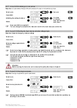
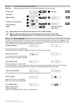
Страница 14: ... KANAL l KANAL 2 CODE Save and return to main menu 4 5 2 Code C003 Seal setpoint Objective Sealing in the setpoints in the main menu A direct change of the values is no longer possible You can only make changes now through code C001 Select code KANAL l KANAL 2 CODE Set code Code C003 KANAL l KANAL 2 CODE Setpoint vibrating amplitude KANAL l KANAL 2 CODE 1 adjustable 0 input inhibited Return KANAL ...

Страница 15: ...low off track 1 relay K1 Track 2 still clear Track 2 sensor 2 full Blow off track 2 relay K2 Track 1 still clear Track 1 Track 2 full Bowl feeder channel 1 Stop about 4 sec later blowing air stop AND logic of the two sensor inputs without blowing off the exit track Bowl feeder channel 1 stops when both sensors are operated Orienting air can be switched off with delay 4 sec via relay K2 OR logic of...

Страница 16: ... The time A 180 sets the maximum duration for which a sensor is allowed to be clear before an alarm message is generated In case of an alarm the relay K2 is clocked on and off Reset takes place automatically when the sensor is operated again If OUT 1 the alarm operates relay K2 indicator light Error and the bowl feeder or linear feeder is stopped An ERROR message appears on the operator panel disp...

Страница 17: ...I active 0 not active Return KANAL l KANAL 2 CODE Save and return to main menu If external voltage application is activated the last digital feed rate set constitutes the minimum feed rate for 0 volt Set the maximum feed rate for 10 volt by the P parameter in C001 Connect the external voltage to terminals 31 32 and 33 in the controller You find the terminals behind the right hand side panel Termin...

Страница 18: ...n the memory even after disconnection from power supply until the message is reset in C009 Overload limitation KANAL l KANAL 2 CODE KANAL l KANAL 2 CODE The output is above the admissible limit Check power input to the feeder and adjust if necessary Check frequency setting Short circuit cut out KANAL l KANAL 2 CODE KANAL l KANAL 2 CODE A short circuit occurred during operation Check cabling and ma...

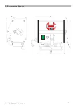
Страница 19: ...Rhein Nadel Automation GmbH 19 VT BA ESR2000_EN 2019 05 08 2019 SJ 5 Dimensional drawing ...

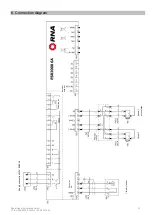
Страница 20: ...Rhein Nadel Automation GmbH 20 VT BA ESR2000_EN 2019 05 08 2019 SJ 6 Connection diagram Supply connection230V 50 60Hz Orienting air Drive max 6A Vibratory feeder External setpoint accumulation ...

Страница 21: ...NA uk com www rnaautomation com Manufacturing and Sales HSH Handling Systems AG Wangenstr 96 CH 3360 Herzogenbuchsee Switzerland Phone 41 0 62 956 10 00 Fax 41 0 62 956 10 10 E mail info handling systems ch www handling systems ch Manufacturing and Sales Pol Ind Famades c Energia 23 E 08940 Cornella de Llobregat Barcelona Spain Phone 34 0 93 377 7300 Fax 34 93 377 6752 E mail info vibrant RNA com ...

Отзывы: