Rittal Liquid Cooling Package
15
3 Device description
EN
The Liquid Cooling Package consists of a solid weld-
ed frame in which the heat exchanger, fan modules,
and the water module are installed.
One wide and one narrow wall plate are mounted on
both the left and right sides.
The wall plates have been punched with air outlet
openings along their entire height in the front section
to ensure cold air supply to the server (LCP Rack) or
to the cold aisle (LCP Inline).
In the LCP Rack, the wall plates in the rear section
have been punched with air inlet openings along their
entire height and width to ensure the dissipation of
warm air from the server.
Seven shelves (or in the case of the LCP Inline flush,
five shelves) are positioned between these wall plates
that divide the front of the Liquid Cooling Package into
several compartments of differing heights. The top
shelf supports the fuse box, the control unit
(CMC III PU), the fan and water PCB, and the startup
current limitation. The compartments for the fans are
below this. All components of the cooling water supply
and condensate management are integrated into the
water module on the floor of the Liquid Cooling
Package.
The front and rear of the Liquid Cooling Package are
each closed with a door with 4-point locking.
In the LCP Rack these doors seal the unit. In the LCP
Inline and LCP Inline flush, the rear door is perforated
to ensure the dissipation of hot air from the hot aisle.
In the LCP Inline flush, the front door is additionally
perforated to ensure the supply of cooling air into the
cold aisle.
The optional display with touch function for operation
in stand-alone mode is located on the front.
3.3.3
Air/water heat exchanger
The air/water heat exchanger is installed in the centre
section of the Liquid Cooling Package between the
two wall plates. In 30 kW units (3311.138/148/238/
538/548), the heat exchanger is covered with a spray
eliminator on the air outlet side that catches any con-
densate and directs it to the condensate collecting
tray at the bottom of the Liquid Cooling Package.
Three temperature sensors are mounted on the rear of
the spray eliminator at the level of the fan modules.
The sensors record the temperature of the cold air in-
take and send it to the control unit.
3.3.4
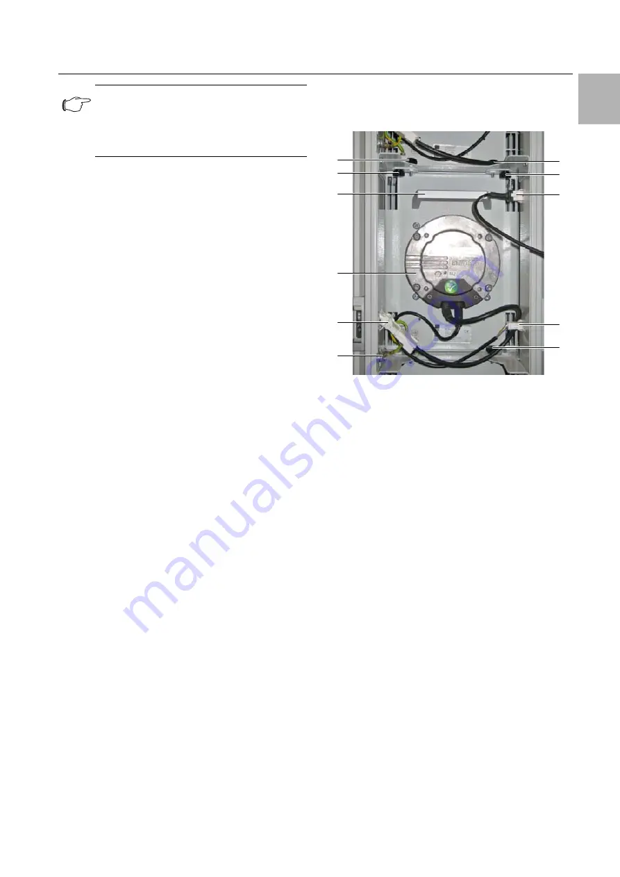
Fan module
Fig. 15:
Fan module in fan tray – LCP Inline and LCP Rack
version
Key
1
Screws
2
Connection cable for display with touch function
3
Connector DC
4
Earth connection
5
Connector AC
6
Fan
7
Handle
Note:
In principle, the rear of the LCP Inline and the
LCP Inline flush looks exactly the same as
the LCP Rack, except that they have a perfo-
rated door.
7
6
1
1
3
2
1
5
1
1
4
Содержание 3311.138
Страница 82: ...16 Further technical information EN 82 Rittal Liquid Cooling Package Fig 89 Fan configuration ...
Страница 93: ......


