RIB2312 Sapphire Gas Log Flame Fire
- 18 -
1/03/18 ©Rinnai
CAUTION
240 Volt exposure. Isolate the electrical supply to the appliance and reconfirm with the
neon screwdriver or multimeter. Disconnect gas supply.
All work should be carried out by qualified service technician
8)
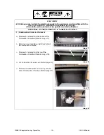
Removal of Gas Control / Ignition Pack
a. Remove 2 x screws in Ignition Pack to access
wiring. (Refer to Image 12).
b. Disconnect gas supply, pilot tube, burner and
gas supply tube. (Refer to Image 13).
c. Remove 3 x screws in Burner Support to remove
Gas Control Mounting Brackets, as shown in
(Refer to Image 14).
Image 12
Image 13
Image 14
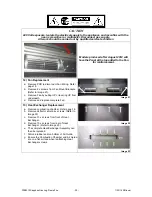
9)
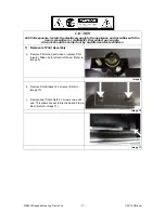
Removal of PCB
a. Remove 2 x screws from either side of the PCB
Bracket. (Refer to Image 15).
b. Carefully lift assembly out, do not strain wiring
loom.
Image 15
10) Removal of Transformer
a. * The Transformer is attached to the rear of the
PCB Bracket by 2 x screws. (Refer Image 16).
b. Remove the 2 x screws and lift the transformer
out.
* Ensure wiring is disconnected before
removing.
Image 16


