background image

RIB2312 Sapphire Gas Log Flame Fire

- 22 -

1/03/18 ©Rinnai

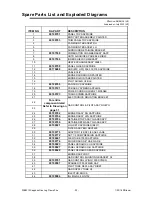
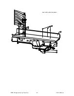
Spare Parts List and Exploded Diagrams

Effective:08/06/16(V4)

Supercedes:July2015(V3)

ITEM NO.

RA PART

DESCRIPTION

1

90199791

PANEL TOP SAPPHIRE

2

BODY OUTER ASSEMBLY PAINTED

3

90199793

TRIM PANEL TOP SAPPHIRE

4

FAN MOUNT BRACKET RH

5

FAN MOUNT BRACKET LH

6

SURROUND RETAINING BRACKET

7

90197538

COMBUSTION CHAMBER ASSY SAPP

8

OUTR AIRGUIDE SPARE BLK RIB23

9

90197539

INNER SHIELD COMB SAPP

10

HEAT EXCHANGE ASSY RIB23

11

90199758

PANEL GLASS SAPPHIRE

12

90176488

OHS (80C OFF) 506 516 318 SAPPHIRE

13

CABLE CLIP

14

BURNER SURROUND PAINTED

15

BURNER AIR INTAKE PAINTED

16

PILOT SHIELD C2 BLK

17

90199760

FAN CONV SAPPHIRE

18

90199721

PCB ASSY SYMBN SAPPHIRE

19

POWER CORD HOLDER 21-MP6N4B

20

90199723

TRANS SYMBN SAPPHIRE

21

ELECTRONICS MOUNTING BRACKET

22

23

24

90199762

BURNER ASSY NG SAPPHIRE

25

90199764

BURNER ASSY LPG SAPPHIRE

26

90199794

RETAINER TOP ASSY GLASS SAPP

27

90199796

RETAINER BTM ASSY GLASS SAPP

28

90198921

LOG SET SAPPHIRE RIB2311

29

FILTER ASSY EMI RDV3600

30

90199770

ADAPTOR 1/2 BSP 3/8 SAE FLARE

31

90199772

NUT 1/2 COMPRESSION SAPPHIRE

32

90199647

FLEXITUBE 1000 SAPPHIRE

33

90199774

PLUG BRASS 3/8" SAE FLARE

34

90198923

PANEL CERAMIC L/H SAPPHIRE

35

90198927

PANEL CERAMIC R/H SAPPHIRE

36

90198929

PANEL CERAMIC REAR SAPPHIRE

37

BURNER SUPPORT

38

GAS CONTROL MOUNTING BRACKET C2

39

90199761

GAS CONTROL LP/NG 1000 SYMBN

40

90199597

SPARKER 1000 SYMBN SAP

41

PILOT TUBE REPL ASSY RIB23

42

GAS SUPPLY TUBE C2

43

INJECTOR BLOCK

44

90198984

INJ MAIN 2.8 NG 752

For entire 

component detail 

Refer to Drawing on 

page 31

GAS CONTROL & PILOT ASSY NG/LPG

Содержание ZERO CLEARANCE

Страница 1: ...SERVICE MANUAL Sapphire RIB2312 GAS LOG FLAME FIRE ...

Страница 2: ...Intentionally Blank ...

Страница 3: ...ealand has been certified to ISO 9001 Quality Assurance by Telarc All Rinnai products carry the C Tick symbol This signifies compliance with the Electromagnetic Compatibility EMC requirements of the Australian Communications Authority ACA which aim to minimise electromagnetic interference Rinnai Australia Supplier Code N10378 ...

Страница 4: ...t wiring This manual has been compiled by Rinnai Australia Engineering Technical Department While many individuals have contributed to this publication it will be successful only if you the reader and customer find it useful We would like to extend an invitation to users of this manual to make contact with us as your feedback and suggestions are valuable resources for us to include as improvements...

Страница 5: ...ble of Contents Introduction 1 Specifications 3 Dimensions 5 Schematic Diagram 6 Operation Principles 7 Fault Analysis 8 Fault Finding 10 Commissioning the Appliance 11 Dismantling for Servicing 14 Wiring Diagram 21 Spare Parts List and Exploded Diagrams 22 ...

Страница 6: ...discharge vent when installed in a masonry chimney or when installed in a zero clearance box or as a stand alone unit through a 100mmø x 150mmø twin skinned flue to the outside of the house This appliance is modular and primarily consists of an Engine that is utilized in any of the 3 configuration types as listed below 1 Fireplace Masonry Engine The appliance is directly mounted into an existing m...

Страница 7: ...evel in decibels A range DC direct current AC alternating current Hz Hertz IC integrated circuit kcal h kilocalorie per hour kPa kilopascals LED light emitting diode mA milliamps MJ h megajoule per hour mm millimetres OHS overheat switch PCB printed circuit board CPU central processing unit POT potentiometer rpm revolutions per minute SV solenoid valve ø diameter C temperature rise above ambient P...

Страница 8: ...80mm 2 speed Centrifugal Gas connection G 1 2 flared male Gas type NG Propane Universal LPG Ignition Continuous Spark Electronic Ignition Input Output Refer data plate and energy rating label on appliance Power Consumption High 50 W Standby 3 0 W 1500 mm cord is supplied with a 3 pin plug Safety Devices Overheat Switch Electrical Fuse Flame Failure Sensing System FFD Power Failure Protection Gas L...

Страница 9: ...BSPT Male brass fitting Pilot assembly Pilot SIT 190 series Internal gas piping Pilot 6mmØ x 1 0mm aluminium Burner 8mmØ x 1 0mm aluminium Remote control IR remote control Weight Engine only 60kgs Convection Fan Double Ø160mm x 180mm 2 speed Centrifugal Glass Primary Ceramic Glass Glass Secondary Dress Guard Tempered Glass Glass seal material Woven fibreglass chord Hytex 1000 by Mid Mountain USA E...

Страница 10: ...ic 865mm 701mm 359mm 76mm 691mm 589mm 305mm 45mm 235mm Zero Clearance Standard 865mm 660mm 363mm 62mm 795mm 650mm 280mm 305mm 45mm 240mm Classic 865mm 701mm 363mm 76mm 795mm 650mm 280mm 305mm 45mm 240mm Console 865mm 760mm 363mm 62mm 865mm 760mm 280mm 305mm 144mm 235mm Plinth 865mm 837mm 363mm 62mm 865mm 837mm 280mm 305mm 219mm 235mm A MASONRY ZERO CLEARANCE PLINTH CONSOLE A A A E E E E B B F F B ...

Страница 11: ...RIB2311 RIB2312 Sapphire Gas Log Flame Fire 6 1 03 18 Rinnai Schematic Diagram ...

Страница 12: ...RIB2312 Sapphire Gas Log Flame Fire 7 1 03 18 Rinnai Operation Principles refer to separate Customer Operation Installation manual section About your Heater page 7 ...

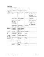
Страница 13: ...staller Repeat lighting procedure Gas valve not opening Check power supply to POV Yellow Yellow DC12V POV resistance 75 85 Ignition failure no spark present Listen if spark is present Check by visual observation that spark is between electrode and Pilot head gap 3 5mm 0 5 Check power supply to ignition box from control unit Blue Black AC216 264V Check condition of ignition probe and check High Ten...

Страница 14: ...S switch activation caused by insufficient flue draw Check if OHS lead is correctly connected to Ignition pack 4 Is there voltage to the ignition pack With the appliance switched on check for voltage at the ignition pack AC216 264V B No spark at Ignition probe 5 Loose high tension lead or cracked damaged ignition probe Check by visual observation that spark is between electrode and Pilot head gap ...

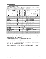
Страница 15: ...nai Australia or your local agent Fault Condition Probable Cause Burners fail to ignite Smell of gas Fan Not Working Minor soot deposits Severe sooting Glass Condensating Glass Streaky lines Remote not working Fault Condition Simplest Possible Remedy Not plugged in or turned off Plug in power cord and turn power ON Mains power failure Re ignition when power restored Initial Install Air in gas pipe...

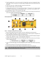
Страница 16: ...e appliance will ignite normally Refer to PCB Control panel image on the next page 3 Press the TEST button twice on the PCB control panel the igniter will spark and the appliance will light to its lowest setting Main burner stage 1 and the display will show PL Refer to table on the next page for correct gas settings data plate values override values printed in this instruction 4 Press the UP butto...

Страница 17: ...positive pressure manometer hose 2 Press the ON OFF button on the PCB control panel to start the ignition sequence the appliance will ignite normally Refer to the PCB control image on the previous page 3 Press the TEST button twice on the PCB control panel the igniter will spark and the appliance will light to its lowest setting Main burner stage 1 and the display will show PL 4 Adjust the pilot f...

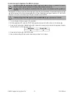
Страница 18: ... button the gas type code will be shown on the display 3 Press the UP button or DOWN button to obtain the correct gas type code for the appliance Refer to the table below for correct gas type code 4 Press the Set button to lock in the code 5 Gas pressure settings should now be checked as per steps 1 and 3 above 240 VOLTS RISK OF ELECTRICAL SHOCK Exercise caution as there is potential for electric ...

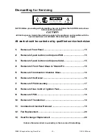
Страница 19: ...e carried out by qualified service technician 1 Remove of Front Panel 15 2 Removal of push button control panel PCB 15 3 Removal of push button control panel label 15 4 Removal of Front Panel Glass Standoff s 16 5 Removal of Combustion Chamber Glass 16 6 Removal of the Burner 16 7 Removal of Pilot Assembly 17 8 Removal of Gas Control Ignition Pack 18 9 Removal of PCB 18 10 Removal of Transformer 1...

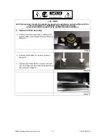
Страница 20: ... Refer Image 2 b Lift Front Panel assembly UP and forward c Disconnect Control Panel Cable from the RJ45 connector located top left Refer Image 3 d Carefully place down Image 1 Image 2 2 Removal of push button control panel PCB a Remove the 2 retaining screws as marked in Image 3 Image 3 3 Removal of push button control panel label a Carefully remove old label taking care not to damage duco b Clea...

Страница 21: ...ass with Standoff s attached will remain on the bench d Remove Standoff s with rubber pads e For replacement of rubber pads and glass follow steps a d in reverse order Image 5 5 Removal of Combustion Chamber Glass a Remove glass surround by lifting bottom section forward and up Refer to image 6 b Remove 2 x M5 screws from Top Glass Retainer c Loosen 2 x M5 screws from Bottom Glass Retainer d Lift ...

Страница 22: ...hould be carried out by qualified service technician 7 Removal of Pilot Assembly a Remove Pilot Head and clean or replace Pilot Injector Slide clip to left and left head Refer to Image 9 Image 9 a Remove Pilot Bracket 2 x screws b Remove Pilot Bracket 2 x screws Refer to Image 10 c Remove pilot front shield 2 x screws one each end This allows access to Electrode and Flame Rod Refer to Image 11 Ima...

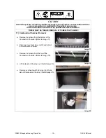
Страница 23: ...nect gas supply pilot tube burner and gas supply tube Refer to Image 13 c Remove 3 x screws in Burner Support to remove Gas Control Mounting Brackets as shown in Refer to Image 14 Image 12 Image 13 Image 14 9 Removal of PCB a Remove 2 x screws from either side of the PCB Bracket Refer to Image 15 b Carefully lift assembly out do not strain wiring loom Image 15 10 Removal of Transformer a The Trans...

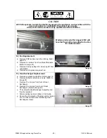
Страница 24: ...TIONS THAT REQUIRE REMOVAL OF COMBUSTION CHAMBER 11 Combustion Chamber Removal a Remove 8 x screws from the bottom of the Combustion Chamber Refer to Image 17 b Disconnect overheat loom right hand side of the combustion chamber c Remove 3 x screws from the top of the Combustion Chamber Refer to Image 18 d Lift Combustion Chamber out Refer Image 19 e Remove overheat switch from rear right hand side...

Страница 25: ... b Remove 2 x screws from Fan Mount Brackets Refer to Image 21 c Remove Fan by pulling UP or levering UP from underneath d Remove and replace complete Fan Image 21 13 Heat Exchanger Replacement a Remove combustion chamber Refer page 14 b Remove deflector shield 4 x screws Refer to Image 22 c Remove 10 x screws from front of Heat Exchanger d Remove 10 x screws from rear of Heat Exchanger Refer to I...

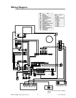
Страница 26: ...Wiring Diagram 63 21752 63 81 7 U EO EO EO EO U 5 5 EN EU EO Z 75 Z Z 5 Z 69 5 5 U EO EO Z 0 20 2 21 2 63 81 7 21 2 J RU EO U JU JU 329 69 69 S Z EO Z Z 7 Z Z U EO SO J RU RU EU EO 1 9 JU JU 5 7 2 7 Z Z EN EN 5 1 5 0 81 21752 02 XUQHU VVXH LJKW 2QO IRU 5 9 ...

Страница 27: ...9 POWER CORD HOLDER 21 MP6N4B 20 90199723 TRANS SYMBN SAPPHIRE 21 ELECTRONICS MOUNTING BRACKET 22 23 24 90199762 BURNER ASSY NG SAPPHIRE 25 90199764 BURNER ASSY LPG SAPPHIRE 26 90199794 RETAINER TOP ASSY GLASS SAPP 27 90199796 RETAINER BTM ASSY GLASS SAPP 28 90198921 LOG SET SAPPHIRE RIB2311 29 FILTER ASSY EMI RDV3600 30 90199770 ADAPTOR 1 2 BSP 3 8 SAE FLARE 31 90199772 NUT 1 2 COMPRESSION SAPPHI...

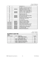
Страница 28: ... HARNESS WIRING SAPPHIRE NOT DRAWN 90199778 HARNESS OHS SAPPHIRE NOT DRAWN 90199688 ELEC CORD 1000 SYMBN SAPPHIRE NOT DRAWN 90199767 HARNESS OHS SYMBN SAPPHIRE NOT DRAWN 90188036 HARNESS PCB TO CTRL 1 4M CAT5 NOT DRAWN 90199782 HARNESS SENSOR SAPPHIRE NOT DRAWN 90199784 HT LEAD SAPPHIRE NOT DRAWN 90150301 INSTALLATION FOAM SEAL Effective 30 10 13 V4 Supercedes 24 06 13 V3 SAPPHIRE FLAME FIRE FRONT...

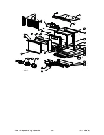
Страница 29: ...RIB2312 Sapphire Gas Log Flame Fire 24 1 03 18 Rinnai 3 6 4 5 1 2 7 ...

Страница 30: ...RIB2312 Sapphire Gas Log Flame Fire 25 1 03 18 Rinnai A 1 3 12 2 13 4 14 24 17 22 26 27 7 11 20 21 19 18 10 15 16 9 28 25 29 5 23 6 32 34 36 35 8 DETAIL A SCALE 1 2 33 30 31 ...

Страница 31: ...RIB2312 Sapphire Gas Log Flame Fire 26 1 03 18 Rinnai 53 49 50 54 55 56 55 44 43 52 51 58 49 48 48 47 39 40 38 37 59 42 41 45 46 57 48 49 GAS CONTROL RIB2310 RIB2311 ...

Страница 32: ... of a local call Higher from mobile or public phones Australia Pty Ltd ABN 74 005 138 769 Internet www rinnai com au E mail enquiry rinnai com au Rinnai has a Service and Spare Parts network with personnel who are fully trained and equipped to give the best service on your Rinnai appliance If your appliance requires service please call our National Help Line Rinnai recommends that this appliance b...

Отзывы: