


31
NOTE
Please refer to 3 - 3E and use the appropriate PPE when
carrying out any of the actions or procedures contained within
this section.
6.1 GAS SUPPLY INSTALLATION
Inspect the entire installation including the gas meter, test for
tightness and purge. Refer to BS 6891 (I.S. 813 in ROI) for
specific instruction.
6.2 THE HEATING SYSTEM
The appliance contains components that may become damaged
or rendered inoperable by oils and/or debris that are residual
from the installation of the system, consequently it is essential
that the system be flushed in accordance with the following
instructions.
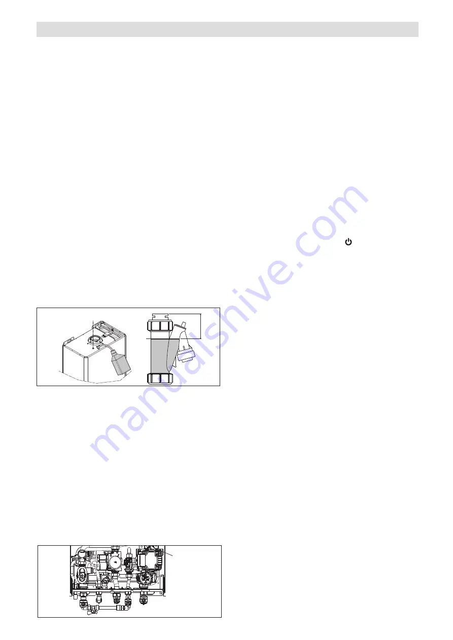
6.3 HOW TO FILL THE CONDENSATE TRAP
The first time you turn the boiler on after a prolonged period of
inactivity or for maintenance work, before using the appliance
you must fill the siphon with water and make sure that the
condensation is evacuated correctly.
Fill the condensation collection siphon pouring 1 litre of water
into the boiler combustion-analysis outlet with the boiler off,
and check that:
- the safety cut-off device is floating
- water is flowing correctly from the discharge pipe out of the
boiler
- the condensate outlet connection line is watertight.
If the condensate outlet circuit (siphon and pipes) is working
correctly, the condensation level will not exceed the maximum.
Filling the siphon before using the appliance, and the use of a
safety cut-off device inside the siphon, prevent exhaust gases
from being released into the environment.
Repeat during standard and non-standard maintenance work.
MAX
~
50 mm
6.4 INITIAL FILLING OF THE SYSTEM
Ensure both flow and return service valves are open, remove
appliance casing as described in 4.5, identify the automatic air
release valves (AAV) and loosen the dust cap/s by turning the
cap anti-clockwise one full turn. Ensure all manual air release
valves located on the heating system are closed. Connect the
filling loop as shown in Fig. 10, slowly proceed to fill the system
by firstly opening the inlet valve connected to the flow pipe, and
then turning the lever on the fill valve, to the open position.
As
water enters the system the pressure will begin to rise. Once
the gauge has reached 1 bar close both valves and begin vent-
ing all manual air release valves, starting at the lowest first. It
may be necessary to go back and top-up the pressure until
the entire system has been filled. Inspect the system for water
tightness, rectifying any leaks.
6.4.1 AUTO AIR VENT (AAV)
When the boiler has been filled for the first time or the system
has been drained and refilled, it will be necessary to release
any air that may have become trapped within the appliance
heat exchanger. Slacken the bleed screw until water is relea-
sed and then close.
AIR
VENT
VALVE
6 COMMISSIONING
6.5 INITIAL FLUSHING OF THE SYSTEM
The whole of the heating system must be flushed both cold
and hot as detailed in 6.9. Open all radiator or heating valves
and the appliance flow & return service valve. Drain the boiler
and system from the lowest points. Open the drain valve full
bore to remove any installation debris from the boiler prior to
lighting. Refill the boiler and heating system as described in 6.4.
6.6 PRE-OPERATION CHECKS
Before attempting the initial lighting of the appliance, the following
checks must b
e carried out:
• ensure all gas service valves from the meter to the appliance
are open and the supply pipe has been properly purged;
• ensure the proper electrical checks have been carried out, (see
8.6) particularly continuity, polarity and resistance to earth;
• ensure the 3 AMP fuse – supplied with the appliance – has
been fitted;
• ensure the system has been filled, vented and the pressure
set to 1 bar;
• ensure the flue system has been fitted properly and in accord
-
ance with the instructions;
• ensure all appliance service valves are open.
6.7 INITIAL LIGHTING
Ensure the electrical supply to the appliance is switched on.
Ensure any external controls are switched to an ‘ON’ position and
are calling for heat. Pressing button 1 the appliance will now
operate as described in 2.2. Should the appliance fail to ignite,
refer to 6.7 and/or section 8 (mode of operation & fault finding).
6.8 CHECKING GAS PRESSURE AND
COMBUSTION ANALYSIS
The appliance is factory set so should require no additional
adjustment once installed. However to satisfy the require-
ments of GSIUR 26/9 (I.S. 813 ROI), it will be necessary to
gas rate the appliance using the gas meter that serves the
appliance and carry out a combustion analysis check in accor-
dance with BS 7967 (UK) to ensure that correct combustion is
occurring, see flow chart
on page 47.
Additionally, if the gas valve has been adjusted, replaced, or
the appliance has been converted for use with another gas
type, then it becomes necessary to carry out a combustion
analysis check to ensure that correct combustion is occurring.
If there are no means to carry out a combustion analysis
check, then it will not be possible to complete the commissio-
ning procedure.
Details on how to carry out the combustion analysis can be
found in section 8.
IMPORTANT
It’s imperative that a sufficient dynamic – gas – pressure is
maintained at all times. Should the dynamic gas pressure fall
below an acceptable level, the appliance may malfunction or
sustain damage.
6.9 FINAL FLUSHING OF THE HEATING
SYSTEM
The system shall be flushed in accordance with BS 7593 (I.S.
813 ROI). Should a cleanser be used, it must be suitable for
Aluminium heat exchangers. It shall be from a reputable manu-
facturer and shall be administered in strict accordance with the
manufacturers’ instructions and the DWTA code of practice.
NOTE
Chemicals used to cleanse the system and/or inhibit corrosion
must be pH neutral, i.e. they should ensure that the level of the
pH in the system water remains neutral. Premature failure of
certain components can occur if the level of pH in the system
water is out-with normal levels.
6.9.1 INHIBITORS
See Section 3 GENERAL REQUIREMENTS (UK).
6.10 SETTING THE FLOW OUTLET TEMPERATURE
The flow outlet temperature can be adjusted between 40 °C - 80
°C for standard CH system by using the buttons
C & D
(Fig. 1).
Fig. 28
Fig. 29