


20173117
40
GB
Maintenance
Boiler
Clean the boiler as indicated in its accompanying instructions in
order to maintain all the original combustion characteristics in-
tact, especially the flue gas temperature and combustion cham-
ber pressure.
Gas leaks
Make sure that there are no gas leaks on the pipe between the
gas meter and the burner.
Gas filter
Change the gas filter when it is dirty.
Combustion
If the combustion values measured before starting maintenance
do not comply with applicable legislation or do not indicate effi-
cient combustion, consult the 7.2.4 or contact our Technical Sup-
port Service to implement the necessary adjustments.
It is advisable to set the burner according to the type of gas used
and following the indications in 7.2.4.
Tab. P
7.2.4
Safety components
The safety components should be replaced at the end of their life
cycle indicated in the following table.
The specified life cycles do not refer to the warranty terms indi-
cated in the delivery or payment conditions.
Tab. Q
7.2.5
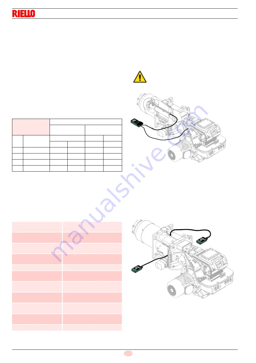
Measuring the ionisation current
The burner is fitted with an ionisation system to check that a
flame is present.
The burner provides a much higher current, so controls are not
normally required.
However, if it is necessary to measure the ionisation current, dis-
connect the plug-socket on the ionisation probe cable and insert
a direct current microammeter with a base scale of 100 µA, as
shown in Fig. 34.
7.2.6
Checking the air and gas pressure on the
combustion head
To carry out this operation it is necessary to use a pressure gauge
to measure the air and gas pressure at the combustion head, as
shown in Fig. 35.
EN 676
Air excess
Max. output
1.2
Min. output
1.3
GAS CO
2
theoretic
a
max. 0% O
2
CO
2
% Calibration
CO
NO
X
= 1.2
= 1.3
mg/kWh mg/kWh
G 20
11.7
9.7
9.0
100
170
G 25
11.5
9.5
8.8
100
170
G 30
14.0
11.6
10.7
100
230
G 31
13.7
11.4
10.5
100
230
Safety
component
Life cycle
Flame control
10 years or 250,000
operation cycles
Flame sensor
10 years or 250,000
operation cycles
Gas valves (solenoid)
10 years or 250,000
operation cycles
Pressure switches
10 years or 250,000
operation cycles
Pressure adjuster
15 years
Servomotor (electronic cam
)(if present)
10 years or 250,000
operation cycles
Oil valve (solenoid)(if pres-
ent)
10 years or 250,000
operation cycles
Oil regulator (if present)
10 years or 250,000
operation cycles
Oil pipes/ couplings (metal-
lic)(if present)
10 years
Flexible hoses (if present)
5 years or 30,000 pressurised cy-
cles
Fan impeller
10 years or 500,000 start-ups
WARNING
Carefully check the polarities!
+
-
-
Fig. 34
20097837
+
-
-
+
20097839
Fig. 35
Checking
air pressure
Checking
gas pressure
Содержание 1135T1
Страница 2: ...Translation of the original instructions...
Страница 29: ...27 20173117 GB Installation Fig 20 No Setpoint air gas Max burner output kW 20081480...
Страница 53: ...51 20169327 GB Appendix Electrical panel layout ALL MODELS RS 310 RS 410 DIRECT START UP...
Страница 54: ...20169327 52 GB Appendix Electrical panel layout RS 310 RS 610 STAR TRIANGLE START UP...
Страница 57: ...55 20169327 GB Appendix Electrical panel layout ALL MODELS...
Страница 58: ...20169327 56 GB Appendix Electrical panel layout ALL MODELS...
Страница 59: ...57 20169327 GB Appendix Electrical panel layout 0 ALL MODELS...
Страница 60: ...20169327 58 GB Appendix Electrical panel layout 0 0 0 1 0 2 0 0 0 0 0 0 0 30 3 3 0 0 1 0 ALL MODELS...
Страница 61: ...59 20169327 GB Appendix Electrical panel layout 0 1 1 1 2 ALL MODELS...
Страница 66: ...20169327 64 GB Appendix Electrical panel layout 0 1 1 1 1 1 2 2 2 0 2 2 2 2 2 2 2 2 2 2 2 0 2 3 ALL MODELS...