background image

Installing the Toner Cartridge

17

2

DDDD

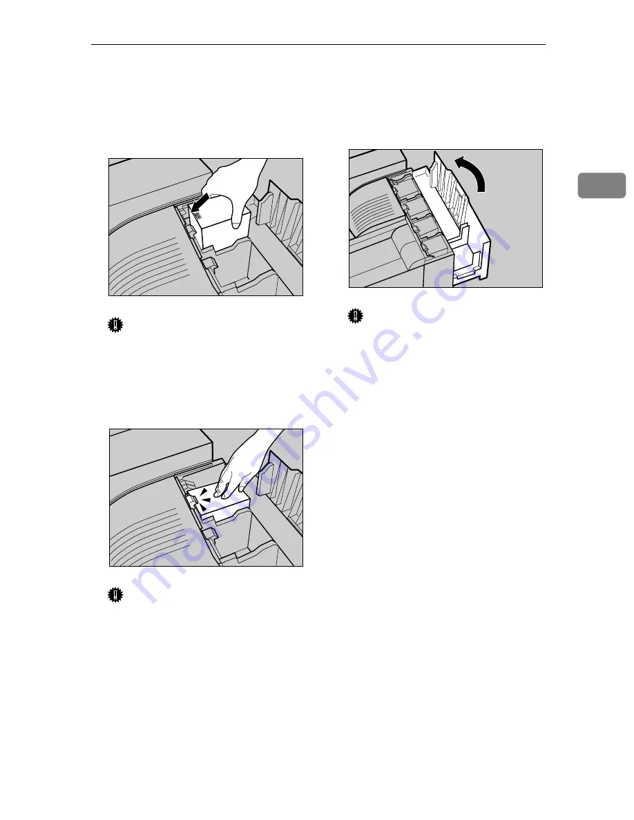
Holding the toner cartridge with
the metal contact area in front, in-
sert in the direction of the arrow.

Insert each cartridge into the same
color slot.

Important

Be careful not to touch the metal
contact point with your fingers.

EEEE

Insert the toner cartridge slowly,
until the green hook snaps on the
metal contact area.

Important

Do not insert and remove toner
cartridges repeatedly, as this
could result in toner leakage.

FFFF

Use the same procedure to insert
the remaining three toner car-
tridges.

GGGG

Close the upper right cover.

Important

Do not turn off the power
switch while “Loading Toner...
” appears on the display to
avoid malfunction.

ZDJT004J

ZDJT005J

ZDJH042J

Содержание CL7000 - Aficio D Color Laser Printer

Страница 1: ...uide For safe and correct use of this machine please be sure to read the Safety Information in the Setup Guide before you use it Guide to Printer Parts Setting Up Preparing to Print Installing Options 1 2 3 4 ...

Страница 2: ...d interlock mechanisms have been designed to prevent any possible laser beam exposure to the operator Important Contents of this manual are subject to change without prior notice In no event will the company be li able for direct indirect special incidental or consequential damages as a result of handling or oper ating the machine Caution Use of controls or adjustment or performance of procedures ...

Страница 3: ...those marks Notes Some illustrations in this manual might be slightly different from the machine Certain options might not be available in some countries For details please con tact your sales or service representative Note The proper names of the Windows operating systems are as follows The product name of Windows 95 is Microsoft Windows 95 The product name of Windows 98 is Microsoft Windows 98 T...

Страница 4: ...ety precautions should always be followed Safety During Operation In this manual the following important symbols are used R WARNING Ignoring this warning could cause serious injury or even death R CAUTION Ignoring this caution could cause injury or damage to property ...

Страница 5: ...or loss of sight If the machine has laser system there is a risk of serious eye dam age If the machine looks damaged or breaks down smoke is coming out there is a strange smell or anything looks unusual immediate ly turn off the operation and main power switches then unplug the power cord from the wall Do not continue using the machine in this condition Contact your service representative If metal...

Страница 6: ...g section because it could be very hot This machine has been tested for safety using this suppliers parts and consumables We recommend you only use these specified supplies Touch only the handles no other parts The fuser oil unit gets very hot and will burn your hands if you touch it Do not eat or swallow toner Keep toner used or unused and toner containers out of reach of chil dren Deliver to col...

Страница 7: ... and dispose of them according to local regulations To avoid possible build up of ozone locate this machine in a large well ven tilated room that has an air turnover of more than 30 m3 hr person When you use this machine for a long time in a confined space without good ventilation you may notice an odd smell To keep the workplace comfortable we recommend that you keep it well ventilated Important ...

Страница 8: ...hine model meets the ENERGY STAR Guidelines for energy efficiency The ENERGY STAR Guidelines intend to establish an international energy saving system for developing and introducing energy efficient office equipment to deal with environmental is sues such as global warming When a product meets the ENERGY STAR Guidelines for energy efficiency the Partner shall place the ENERGY STAR logo onto the ma...

Страница 9: ... this instruction is not followed paper might be misfed or data might be lost Be sure to read this Preparation This symbol indicates the prior knowledge or preparations required before op erating Note This symbol indicates precautions for operation or actions to take after misop eration Limitation This symbol indicates numerical limits functions that cannot be used together or conditions in which ...

Страница 10: ... the Optional Paper Feed Unit 19 2000 sheet Large Capacity Tray 20 Turning the Power On 21 Selecting the Display Language 22 Test Printing 23 3 Preparing to Print Connecting the Printer 25 Connecting to a Network 25 Parallel Connection 26 Configuring the Printer for the Network using the Control Panel 27 Installing the Printer Driver 30 4 Installing Options Installing Options 33 Using the Screwdri...

Страница 11: ... A 57 IEEE 802 11b wireless LAN Configuration 60 Bluetooth Unit Type 2045 64 User Account Enhance Unit TypeC 67 Printer Hard Disk Type 7000 70 Formatting the Printer Hard Disk Drive 73 Duplex Unit Type 7000 74 Installing the Duplex Reversal Unit Stand 74 Installing the Duplex Reversal Unit 77 Installing the Duplex Feed Unit 79 SR770 2 Tray Finisher 81 Mail Bin Type 3800C 4 bin Mailbox 87 INDEX 91 ...

Страница 12: ...x ...

Страница 13: ...hotocon ductor unit A screwdriver is attached to this cover 4 Power switch Use this to switch between power on and off 5 Tray 1 Loads up to 500 sheets of plain paper tray for printing Only for 11 8 1 2K paper 6 Tray 2 Loads up to 500 sheets of plain paper tray for printing 7 Standard tray Output is stacked here with the print side down Note If printed A3 short edge feed or 11 17 short edge feed sh...

Страница 14: ...face cable and Ethernet cable into their con nectors 11 Parallel port Use a parallel cable to connect the printer to the host computer 12 Ethernet port Use a network interface cable to connect the printer to a network 13 Bypass tray extension Pull this out to load paper in the bypass tray when its length is longer than A4 L 14 Bypass tray Use to print on thick paper OHP trans parencies custom size...

Страница 15: ...the cable for the duplex reversal unit to this port 4 4 bin mailbox 2 tray finisher port Connect the cable for the 4 bin mailbox or the 2 tray finisher to this port 5 Power port Connect the power cable to this port and the other end to the wall outlet 6 Upper left cover Open this to remove misfed paper or when replacing the fusing unit 7 External tray Printed output is stacked here with the print ...

Страница 16: ...r unit or development unit 5 Photoconductor unit The printer comes with one black and three color yellow cyan and magenta photoconductor units 6 Development unit The printer comes with one black devel opment unit and three color yellow cy an magenta development units 7 Toner cartridge Loads from the printer rear in the order of magenta M cyan C yellow Y and black K 8 Waste oil bottle Collects oil ...

Страница 17: ...per size or type does not match the actually set size or type 5 Menu key Press this to make and check current printer settings 6 Power indicator This indicator remains lit while the pow er is on It is unlit when the power is off or while the printer is in Energy Saver mode 7 Error indicator Lights up whenever a printer error oc curs However it is unlit in Energy Saver mode 8 Data In indicator Blin...

Страница 18: ...Guide to Printer Parts 6 1 ...

Страница 19: ... bend it more than necessary These actions could damage the cable A frayed or damaged cable might cause an electrical fire hazard Do not handle the plug with wet hands Doing so might cause an electri cal shock Keep the machine in an area that is within optimum environmental con ditions Operating the machine in an environment that is outside the rec ommended ranges of humidity and temperature can c...

Страница 20: ...ows A 46 cm 19 inch or more B 10 cm 4 inch or more C 55 cm 22 inch or more D 70 cm 28 inch or more Optimum Environmental Conditions Permissible and recommended temperature and humidity ranges are as fol lows White area Permissible Range Gray area Recommended Range ZDJX005J B A C D 50 F 80 80 6 F 80 77 F 70 77 F 30 89 6 F 54 89 6 F 15 50 F 15 59 F 30 59 F 70 80 60 40 20 50 80 90 60 70 RH F ...

Страница 21: ...good ventilation you may detect an odd smell To keep the workplace comfortable we recommend you keep it well ventilated Environments to Avoid Important Areas exposed to direct sunlight or strong light Dusty areas Areas with corrosive gases Areas that are excessively cold hot or humid Locations near air conditioners or humidifiers Locations near other electronic equipment Locations subject to frequ...

Страница 22: ...are missing items contact your sales or service representative Manuals and CD ROMs Manuals for This Printer Setup Guide This manual Maintenance Guide CD ROM Printer Drivers and Utilities CD ROM Operating Instructions CD ROM Document Management Utility Parts External Tray Power Cable Ferrite Core Fuser Oil Unit ...

Страница 23: ...ner Cartridge K Magenta M Cyan C Yellow Y Toner Cartridges Paper Feed Unit Labels Additional Documentation Note This package does not include an interface cable Please purchase one to use with your host computer See Appendix Administrator Reference ...

Страница 24: ... the adhesive tape and sheet of paper D D D D Close Tray 1 slowly E E E E Open Tray 2 F F F F Remove the adhesive tape and sheet of paper G G G G Close Tray 2 slowly H H H H Open the front cover slowly by pulling down using the upper left and right sides Important Do not place objects on the opened front cover ZDJH001J ZDJH003J ZDJH004J ZDJH005J ZDJH006J ZDJH007J ...

Страница 25: ...ur piec es of tape to avoid printer mal function during operation The removed tape is dirty Be careful not to let it touch your hands or clothes L L L L Remove the securing pin as shown from the transfer unit Pinch it and then pull it out M M M M Close the front cover slowly by pushing the two areas on the left and right N N N N Put labels 1 and 2 on the front of the paper trays ZHXHK110J ZHXH420J...

Страница 26: ...wly pull it A A A A out Fi nally hold the upper part of seal B B B B and then slowly peel it off Note Be sure to remove seal A and then pull it out horizontally Important Be sure to remove the seals to avoid printer malfunction Be sure to remove seal A first and then remove seal B to avoid oil leakage After removing the seals be careful not to let oil from oil supplying parts or the seals come int...

Страница 27: ...fuser oil unit Insert the fuser oil unit firmly until it stops E E E E Slowly turn the fuser unit handle in the direction of the arrow until it clicks F F F F Close the upper left cover A A A A and then push the part labeled PUSH next to the handle at the bottom rear until it clicks B B B B G G G G Attach the external tray to the printer Insert the hooks of the ex ternal tray into the printer slit...

Страница 28: ...e out the toner cartridges from the box Note The black K toner cartridge contains more toner than the others C C C C Shake the toner cartridge back and forth five or six times Do not incinerate spilled toner or used toner Toner dust is flammable and will ignite when exposed to an open flame Disposal should take place at an authorized dealer or an ap propriate collection site If you dispose of the ...

Страница 29: ... your fingers E E E E Insert the toner cartridge slowly until the green hook snaps on the metal contact area Important Do not insert and remove toner cartridges repeatedly as this could result in toner leakage F F F F Use the same procedure to insert the remaining three toner car tridges G G G G Close the upper right cover Important Do not turn off the power switch while Loading Toner appears on t...

Страница 30: ...nly For details about size and feed orien tation of paper that can be loaded in the tray see Paper and Other Me dia Maintenance Guide For details about loading paper in the bypass tray see Loading Paper in the Bypass Tray Maintenance Guide Loading Paper in Tray 1 Important Tray 1 is 11 8 1 2K paper only Load only 11 8 1 2 size paper A A A A Slowly slide the paper tray out until it stops B B B B Al...

Страница 31: ...y out until it stops B B B B Adjust the side guide according to the size and orientation of the paper as follows A Release the side guide lock B Press the green lever of the side guide A A A A and then adjust the po sition of the guide by moving it in the direction of the arrow B B B B C C C C Adjust the end guide according to the size and orientation of the pa per by gripping both edges of the gu...

Страница 32: ...If you want to A4 paper in the 2000 sheet Large Capacity Tray optional contact your sales or service representative A A A A Slowly slide the paper tray out until it stops B B B B Align all four sides of the paper stack and then load two stacks next to each other Important Be sure to align the paper and load them against the left and right walls or a paper misfeed could occur Make sure the top of t...

Страница 33: ...or on the back of the printer C C C C Plug in the power cable Important Make sure the power cable is plugged securely into the wall outlet Turn the power switch off when plugging and unplugging the power plug D D D D Turn the power switch to a a a a On Plug and unplug the power ca ble with dry hands or an elec tric shock could occur ZDJH029J ZDJH030J ZDJH031J ...

Страница 34: ... T T to display Lan guage C C C C Press Enter The following message appears on the display D D D D Press U U U U or T T T T until the lan guage you want to select appears E E E E Press Enter Wait for two sec onds The menu appears on the display F F F F Press On Line Ready message appears on the display Menu Language On Line Menu Job Reset Escape Enter Form Feed Power Error Data In ZDJS001N Languag...

Страница 35: ... then press Enter The menu for selecting the con tents to be test printed appears C C C C Press U U U U or T T T T to display the Config Page and then press Enter The following message appears and the configuration page is printed Note If printing is not normal check to see if an error message ap pears on the display If there is an error message see Trouble shooting Maintenance Guide D D D D Check...

Страница 36: ...Setting Up 24 2 ...

Страница 37: ...st to the printer C C C C Connect the network interface ca ble to the port on the right side of the printer D D D D Connect the other end of the cable to the network such as a hub con nection For details about network environ ment settings see Administrator Reference Reading the LED lamps 1 Yellow lights up when 100BASE TX is being used Turns off when 10BASE T is being used 2 Green lights up when ...

Страница 38: ... parallel port on the host computer Use shielded interface cables Us ing unshielded cables could result in radio interference noise A A A A Turn off the printer and comput er B B B B Attach the parallel cable to the printer s port Secure the cable with the metal fittings as shown Important Voltage rating of the parallel port for the computer max DC 5V C C C C Attach the other end of the paral lel ...

Страница 39: ...nu appears on the display B B B B Press U U U U or T T T T to display Host Interface and then press Enter The interface setting menu ap pears C C C C The procedure below describes how to set TCP IP Make settings for other items by following the same procedure Note The default settings for all pro tocols are Active You are recommended to set unused protocols Not Active A Press U U U U or T T T T to...

Страница 40: ...t make settings for the following items IP Address Subnet Mask Gateway Address Note Consult your network adminis trator for information about making network settings A Set DHCP to Off B Press U U U U or T T T T to display DH CP and then press Enter C Press U U U U or T T T T to display Off and then press Enter The current IP address appears on the display Note shows the current setting After about...

Страница 41: ...address used as a net work address Confirm the val ue with the network administrator The gateway address is the ad dress of the host or router that acts as a gateway when interact ing with work stations on an other network Confirm the value with the network admin istrator Note If you are not sure about ad dress settings leave them as de fault F F F F When all settings are made press On Line Ready ...

Страница 42: ...indows 2000 Windows XP and Windows NT 4 0 When using TCP IP confirm the fol lowing The printer is connected to a net work with ethernet cable TCP IP is set IP addresses are set for the printer and the computer A A A A Insert the CD ROM labeled Printer Drivers and Utilities into the CD ROM drive Auto Run will start the installer B B B B Select a language for the inter face and then click OK The fol...

Страница 43: ...P address is displayed in Connect to For parallel connection select the printer whose printer port is displayed in Connect to F F F F Click Install The following display appears when installing the printer driver When finished the Installation Completion dialog box appears G G G G Click Finish Note A message directing you to re start the computer may appear If this happens restart your computer to...

Страница 44: ...Preparing to Print 32 3 ...

Страница 45: ... If the cable is unplugged with sudden force it could become damaged Damaged plugs or cables can cause an electrical fire hazard When lifting the machine use the grips on both sides The machine could break or cause injury if dropped A Attach the 500 1000 sheet pa per feed unit or 2000 sheet Large Capacity Tray Paper Feed Unit Type 3800C Paper Bank PS470 Attach the paper feed unit to the bottom of ...

Страница 46: ...nit slot of the controller board T E Install the printer hard disk Printer Hard Disk Type 7000 Install the Printer Hard Disk Type 7000 to the controller board T F Attach the duplex unit Duplex Unit Type 7000 Attach the duplex reversal unit to the left side of the print er and the duplex feed unit inside the printer T G Attach the 2 tray finisher SR770 Attach the 2 tray finisher to the left side of...

Страница 47: ...s up to 2 000 sheets 2 000 sheets 1 column of paper See p 43 Installing the Paper Bank PS470 2000 sheet Large Capacity Tray 4 SR770 2 Tray Finisher Performs Job Separation staples and punches holes Install the finisher on the left side of the printer See p 81 SR770 2 Tray Finisher 5 Mail Bin Type 3800C 4 bin Mail box Sorts printed documents from multi ple users Attach the mailbox to the top of the...

Страница 48: ... finisher and 4 bin mailbox at the same time Interior 1 Memory Unit TypeC SDRAM Module Install 64 MB 128 MB or 256 MB RAM into the controller board slot See p 46 Memory Unit TypeC SDRAM Module 2 1394 interface unit USB interface board 802 11b interface unit Blue tooth unit See p 48 1394 Interface Unit Type 4510 See p 54 USB 2 0 Interface Board Type A See p 57 802 11b Interface Unit Type A See p 64...

Страница 49: ... attaching options is attached to the inside of the front cover By pushing the screw top into the screwdriver you can work with out having to worry about dropping the screw Note After using the screwdriver return it to its original position on the inside of the front cover ZHXH170J ...

Страница 50: ...ll the paper feed unit Start installa tion when all four people are ready R CAUTION Note The printer weighs approximately 85 kg 187 lbs Installing the Paper Feed Unit Type 3800C 500 1 R CAUTION Note The 500 sheet paper feed unit weighs approximately 18 kg 39 7 lbs A A A A Turn off the power and then un plug the power cable B B B B Remove the adhesive tape C C C C Adjust the four corners of the pri...

Страница 51: ...and the corrugated paper inside the tray as shown E E E E Take out the packaged items making sure there are two thumb screws and one mounting brack et Close the tray of the 500 sheet paper feed unit firmly F F F F Slowly pull out Tray 2 while lift ing up a little G G G G Fasten one thumb screw A coin can be used to fasten the screws H H H H Slowly slide Tray 2 back into the printer until it stops ...

Страница 52: ...nt of the 500 sheet paper feed unit Note After finishing the installation you can check the 500 sheet pa per feed unit is installed proper ly Print the configuration page from the List Test Print menu If it is installed properly you will see Paper Feed Unit Tray 3 appear under the Op tions list If the paper feed unit is not in stalled properly repeat the pro cedure from step A If you cannot instal...

Страница 53: ...00 sheet paper feed unit and then slowly lower the printer into place Important Four people should hold the handles located on two sides of the printer to move it D D D D Open the tray of the 1000 sheet paper feed unit A Remove the adhesive tape and sheet of paper B Remove the adhesive tape and the corrugated paper inside the tray as shown When moving the paper feed unit hold the bottom of both si...

Страница 54: ...en one thumb screw A coin can be used to fasten the screws H H H H Slowly slide Tray 2 back into the printer until it stops I I I I Open the right cover of the 1000 sheet paper feed unit J J J J Hook the mounting bracket to the hole as shown K K K K Fasten the bracket with the other thumb screw A coin can be used to fasten the screws L L L L Close the right cover of the 1000 sheet paper feed unit ...

Страница 55: ...ou cannot install it properly even after reinstallation contact your sales or service representative Reference p 23 Test Printing Installing the Paper Bank PS470 2000 sheet Large Capacity Tray R CAUTION Note The 2000 sheet Large Capacity Tray weighs approximately 25 kg 55 2 lbs A A A A Turn off the power and then un plug the power cable B B B B Remove the adhesive tape C C C C Adjust the four corn...

Страница 56: ... the tray of the 2000 sheet Large Capacity Tray firmly E E E E Slowly pull out Tray 2 while lift ing up a little F F F F Fasten one thumb screw A coin can be used to fasten the screws G G G G Slowly slide Tray 2 back into the printer until it stops H H H H Open the right cover of the 2000 sheet Large Capacity Tray I I I I Hook the mounting bracket to the hole as shown ZDJP007J ZDJP005J ZHXH851J ZD...

Страница 57: ...er finishing the installation you can check the 2000 sheet Large Capacity Tray is installed properly Print the configura tion page from the List Test Print menu If it is installed properly you will see LCT Tandem Bank appear under the Options list If the paper feed unit is not in stalled properly repeat the pro cedure from step A If you cannot install it properly even after reinstallation contact ...

Страница 58: ...emove the green screw driver and then close the cover Reference p 37 Using the Screwdriver C C C C Remove the two screws fastening the controller board to the back of the printer using the provided screwdriver The removed screws will be used later to fasten the controller board D D D D Holding the handle slowly pull out the controller board E E E E Put the controller board down on a flat surface F...

Страница 59: ...to return the provided screwdriver to its original posi tion on the inside of the front cover After finishing the installation you can check the memory unit is installed properly Print the configuration page from the List Test Print menu If it is installed properly you will see the memory capacity for Total Memory If the memory unit is not in stalled properly repeat the pro cedure from step A If y...

Страница 60: ...dling the 1394 interface unit ground yourself by touching something metal to discharge any static electricity Static electricity can damage the 1394 interface unit Unplug all interface cables from the printer before installation If you take out the controller board with cables still plugged in the 1394 interface unit might be dam aged Do not plug or unplug the 1394 in terface cable while installin...

Страница 61: ...emove the small cover plate us ing the provided screwdriver as shown Note The removed screws will be needed in step I H H H H Install the 1394 interface unit into the controller board Insert the tip of the 1394 interface unit into the attachment area A A A A and then push it in the direction of the ar row B B B B Check the 1394 interface unit is connected firmly to the controller board I I I I Usi...

Страница 62: ...and then check the items in System Reference If it is installed prop erly you will see IEEE1394 ap pear under Controller Option If the 1394 interface unit is not installed properly repeat the procedure from step A If you cannot install it properly even after reinstallation contact your sales or service representative Reference p 23 Test Printing Connecting the Cable to the 1394 Interface Unit A A ...

Страница 63: ... Enter The following message appears on the display F F F F Press U U U U or T T T T to display IP over 1394 A Press Enter B Press U U U U or T T T T to select ei ther Active or Not Active C Press Enter After a few seconds the display returns to the previous menu Setting Name Value IP Address1394 000 000 000 000 Subnet Mask1394 000 000 000 000 IP over 1394 Active SCSI print Active Bidi SCSI print ...

Страница 64: ...ape If you press Escape when the cursor k is in the left most position the selected IP address is reset E Repeat steps C C C C and D D D D to enter the IP address Check the cursor k is in the rightmost position and then press Enter to register the IP address you selected H H H H Set Subnet Mask1394 in the same way I I I I Set SCSI print and Bidi SCSI print if necessary Note The default is Active J...

Страница 65: ...1394 Interface Unit Type 4510 53 4 M M M M Press On Line Ready appears on the display N N N N Print a configuration page to con firm the settings made See p 23 Test Printing Ready ...

Страница 66: ...dling the USB 2 0 inter face board ground yourself by touching something metal to dis charge any static electricity Static electricity can damage the USB 2 0 interface board Do not subject the USB 2 0 inter face board to physical shocks Buy a USB cable suitable for your computer A A A A Check the contents of the box USB 2 0 Interface Board Type A B B B B Turn off the power and then un plug the pow...

Страница 67: ... be needed in step I H H H H Install the USB 2 0 interface board into the controller board Insert the tip of the USB 2 0 inter face board into the attachment area A A A A and then push it in the direction of the arrow B B B B Check the USB 2 0 interface board is connected firmly to the control ler board I I I I Using the screwdriver provided tighten the two screws removed in step G G G G securing ...

Страница 68: ...figuration page from the List Test Print menu and then check the items in System Reference If it is in stalled properly you will see USB appear under Control ler Option If the USB 2 0 interface board is not installed properly repeat the procedure from step A If you cannot install it properly even after reinstallation contact your sales or service representa tive Reference p 23 Test Printing Connec...

Страница 69: ... problems occur with printing due to of poor radio reception connect an external antenna A A A A Check the contents of the box 802 11b Interface Unit Type A Interface Unit Card B B B B Turn off the power and then un plug the power cable and inter face cable C C C C Slowly open the front cover of the printer remove the green screw driver and then close the cover Reference p 37 Using the Screwdriver...

Страница 70: ... needed in step I H H H H Install the 802 11b interface unit into the controller board Insert the tip of the 802 11b interface unit into the attachment area A A A A and then push it in the direction of the arrow B B B B Check the 802 11b interface unit is connected firmly to the controller board I I I I Using the screwdriver provided tighten the two screws removed in step G G G G securing the 802 ...

Страница 71: ...re to return the provided screwdriver to its original posi tion on the inside of the front cover After finishing the installation you can check the 802 11b inter face unit is installed properly Print the configuration page from the List Test Print menu and check the items in System Reference If it is in stalled properly you will see IEEE 802 11b appear under Controller Option If the 802 11b interf...

Страница 72: ...the Control Panel A A A A Press Menu The menu appears on the display B B B B Press U U U U or T T T T to display Host Interface menu C C C C Press Enter The following message appears on the display D D D D Press U U U U or T T T T to display IEEE 802 11b E E E E Press Enter Check that Comm Mode ap pears on the display F F F F Press Enter The following message appears on the display Setting Name De...

Страница 73: ...r J J J J Set Trans Speed in the same way Note The default is Auto If you need to change the transmitting speed depending on the envi ronment you are using select the appropriate speed K K K K Press the U U U U or T T T T key to dis play SSID and then press the Enter key The following message appears on the display Note The default is ASSID If an SSID has been set you can check it Press the U U U ...

Страница 74: ...have entered the WEP key and then change the set ting press the U U U U or T T T T key to display No and then press the Enter key C Press the Enter key Note The value in brackets at the upper right indicates the number of characters en tered D Press the U U U U or T T T T key to se lect characters and then press the Enter key The cursor k moves to the next character position E Continue entering No...

Страница 75: ... After entering press the Enter key The screen returns to step L M M M M Press On Line Ready appears on the display N N N N Print a configuration page to con firm the settings made See p 23 Test Printing WEP Key 26 0000000000000000 Ready ...

Страница 76: ...rence The manual provided with the Bluetooth unit A A A A Check the contents of the box Bluetooth Interface Unit Card Antenna Cap B B B B Turn off the power and then un plug the power cable and inter face cable C C C C Slowly open the front cover of the printer remove the green screw driver and then close the cover Reference p 37 Using the Screwdriver D D D D Remove the two screws fastening the co...

Страница 77: ...te The removed screws will be needed in step I H H H H Install the Bluetooth unit into the controller board Insert the tip of the Bluetooth unit into the attach ment area A A A A and then push it in the direction of the arrow B B B B Check the Bluetooth unit is con nected firmly to the controller board I I I I Tighten the two screws fastening the Bluetooth unit using the pro vided screwdriver ZDJP...

Страница 78: ... the antenna cap over the antenna Note Be sure to return the provided screwdriver to its original posi tion on the inside of the front cover After finishing the installation you can check the Bluetooth unit is installed properly Print the configuration page from the List Test Print menu If it is installed properly you will see Bluetooth appear under Controller Option If the Bluetooth unit is not i...

Страница 79: ... A A A Check the contents of the box User Account Enhance Unit One Screw B B B B Turn off the power and then un plug the power cable C C C C Slowly open the front cover of the printer remove the green screw driver and then close the cover Reference p 37 Using the Screwdriver D D D D Remove the two screws fastening the controller board to the back of the printer using the provided screwdriver The r...

Страница 80: ...ount enhance unit A A A A and then push the unit in the di rection of the arrow B B B B Check the user account enhance unit is connected firmly to the con troller board H H H H Tighten the screw fastening the user account enhance unit using the provided screwdriver I I I I Align the controller board with the top and bottom rails and then push in slowly until it stops J J J J Tighten the two screws...

Страница 81: ...nhance unit is installed proper ly Print the configuration page from the List Test Print menu If it is installed properly you will see Accounting Mod ule appear under Controller Option If the user account enhance unit is not installed properly repeat the procedure from step A If you cannot install it properly even after reinstallation contact your sales or service representa tive Reference p 23 Te...

Страница 82: ...ck the contents of the box Printer Hard Disk Type 7000 Flat Cable Power Cable Two Screws B B B B Turn off the power and then un plug the power cable C C C C Slowly open the front cover of the printer and remove the green screwdriver and then close the cover Reference p 37 Using the Screwdriver D D D D Remove the two screws fastening the controller board to the back of the printer using the provide...

Страница 83: ...troller board H H H H Tighten the two screws fastening the printer hard disk to the con troller board using the provided screwdriver I I I I Connect the power cable and flat cable to the printer hard disk J J J J Connect the flat cable to the con troller board K K K K Remove the white clamp from un der the printer hard disk and then open it as shown ZDJP025J ZHXP301J ZHXP311J ZHXP321J ZHXP082J ZHX...

Страница 84: ... board with the top and bottom rails and then push in slowly until it stops P P P P Tighten the two screws fastening the controller board back into its original position using the pro vided screwdriver The printer hard disk automatical ly begins formatting when the printer is switched on Note Be sure to return the provided screwdriver to its original posi tion on the inside of the front cover ZHXP...

Страница 85: ...ss Menu The menu appears on the display B B B B Press U U U U or T T T T to display Maintenance and then press Enter The menu for selecting Mainte nance items appears C C C C Press U U U U or T T T T to display HDD Format and then press Enter A check message appears Note If HDD Format is not dis played on the display the print er hard disk is not installed properly Repeat the procedure from step A...

Страница 86: ...N Installing the Duplex Reversal Unit Stand A A A A Check the contents of the box Stand Paper Guide One Short Screw Four Long Screws Duplex Reversal Unit Duplex Feed Unit The inside of the machine be comes very hot Do not touch the parts labelled hot surface Touching a hot surface could result in a burn Do not let go of the duplex rever sal unit until it is fastened in place It could fall and caus...

Страница 87: ...then un plug the power cable from the wall outlet D D D D Slowly open the front cover of the printer remove the green screw driver and then close the cover Reference p 37 Using the Screwdriver E E E E Lift the external tray in the direc tion of the arrow A A A A and then re move B B B B F F F F Remove the two small covers on the upper left cover of the printer A Open the upper left cover B Remove ...

Страница 88: ...and Hold it so that the right side bends down as shown and then while gripping lightly A A A A insert it into the holes of the stand B B B B I I I I Insert the claws of the stand into the holes on the left side of the printer A A A A and then push down B B B B J J J J Tighten the four long screws fas tening the duplex reversal unit stand using provided screwdriv er Fasten in the order of A A A A B...

Страница 89: ...he bar inside the groove of the stand B B B B While supporting the duplex re versal unit remove the stopper the printer s mounting bracket This stopper will be used in a later step E so take care not to lose it C C C C While supporting the duplex re versal unit remove the adhesive tape and then hold the auxiliary bar in front of the hook on the left side and then stand it up D D D D Hook the hole ...

Страница 90: ...ld ings the cable and then connect the cable from the duplex reversal unit to the upper connector on the back of the printer This completes installation of the duplex reversal unit Install the duplex feed unit after the external tray H H H H Install the external tray A Stand the external tray and then insert it from the left side using both hands B Pushing the right edge of the external tray light...

Страница 91: ...rection of the arrow R CAUTION C C C C Holding the duplex feed unit us ing both hands place it on the vertical rail and then slide it slowly in until it stops The vertical rail is in the position as shown D D D D Fasten the duplex feed unit using a short screw and the provided screwdriver Keep the waste oil bottle away from flames There is a risk of fire or burns ZDJH007J ZHXH150J ZHXH290J ZHXH300...

Страница 92: ... left and right Note After finishing the installation you can check the duplex unit is installed properly Print the configuration page from the List Test Print menu If it is installed properly you will see Duplex Unit appear in the Options list If the duplex unit is not installed properly repeat the procedure from step A If you cannot in stall it properly even after rein stallation contact your sa...

Страница 93: ... duplex unit with options are installed The 2 tray finisher requires the op tional printer hard disk or optional memory unit with at least 64 MB total memory size 128 MB or more You cannot install the 4 bin mail box and 2 tray finisher at the same time A A A A Turn off the power and then un plug the power cable B B B B Remove the adhesive tape and packing materials Important Do not remove the adhe...

Страница 94: ...nisher Trays D D D D Slowly open the front cover of the printer remove the green screw driver and then close the cover Reference p 37 Using the Screwdriver E E E E Stand the external tray of the printer A Stand it vertically B Fold it over the top of the print er F F F F Insert the rail with a wheel in the mounting bracket ZDJP061J ZHXH330J ZHXH340J ZDJP066J ...

Страница 95: ...astened in step G G G G J J J J Holding the mounting bracket using both hands move it in the direction of up A A A A to the right B B B B K K K K With the left corner of the mount ing bracket in the position point ed by the arrow on the printer fasten the left side of the mount ing bracket using a long screw and the provided screwdriver Also tighten the screw on the right side temporarily fastened...

Страница 96: ...porarily tightened in step L L L L Note If you have the 1000 sheet paper feed unit or 2000 sheet Large Capacity Tray installed pro ceed to step P O O O O If you have the 500 sheet paper feed unit installed change the position of the connecting bracket on the side of the 2 tray finisher to the low er level Remove the two screws us ing the provided screwdriver then move the connecting bracket down a...

Страница 97: ...astening the ca ble to the 2 tray finisher T T T T Connect the cable of the 2 tray fin isher to the lower connector on the back of the printer U U U U Place the two 2 tray finisher trays in the 2 tray finisher Note The two finisher trays are iden tical A Adjust the notch on the left side of the 2 tray finisher tray to the cable coming out from the 2 tray finisher ZDJP078J ZHXH350J ZDJP080J ZDJP082...

Страница 98: ... V V V Put the finisher tray installed on the duplex unit back in place A Lift the top B Lower slowly Note After finishing the installa tion you can check the fin isher is installed properly Print the configuration page from the List Test Print menu If it is installed prop erly you will see 2 Tray Fin isher appear in the Options list If the Finisher is not installed properly repeat the proce dure ...

Страница 99: ...ant Do not remove the adhesive tape fastening the cable yet Re move it in step N C C C C Check the contents of the box Two Screws Four Output Bins Labels D D D D Slowly open the front cover of the printer remove the green screw driver and then close the cover Reference p 37 Using the Screwdriver E E E E Remove the top cover Draw the lever A A A A and then lift B B B B to re move it When moving the...

Страница 100: ...o the openings and then insert until you hear a click If the duplex unit is installed pro ceed to step H G G G G Pull up the external tray in the di rection of the arrow A A A A and then remove B B B B H H H H If the duplex unit is installed open the duplex reversal unit A Push up the lock release but ton and leave it in that posi tion B Slowly lower the duplex rever sal unit until it stops ZDJP08...

Страница 101: ...f the front cover K K K K Close the upper left cover If the duplex unit is installed pro ceed to step M L L L L Install the external tray into the printer Hook the external tray the printer s slits and then lower the tray toward you M M M M If the duplex unit is installed re turn the duplex reversal unit to its original position Lift slowly un til you hear a click N N N N Remove the adhesive tape ...

Страница 102: ... on the labels provided and stick them to the sides of the 4 bin mailbox Note After finishing installation you can check the 4 bin mailbox is installed properly Print the configuration page from the List Test Print menu If it is installed properly you will see 4 bin Mailbox appear under the Options list If the 4 bin mailbox is not in stalled properly repeat the pro cedure from step A If you cannot...

Страница 103: ...22 Duplex Unit Duplex Feed Unit 36 Duplex Reversal Unit 35 Duplex Unit Port 3 Duplex Unit Type 7000 74 Dustproof Filter 3 E Energy Star vi Ethernet 27 Ethernet Port 1 External Tray 3 F Frame type NetWare 27 Front Cover 1 Fuser Oil Unit 4 14 Fusing Unit 4 G Gateway Address 27 Guide to the Printer Control Panel 5 Exterior Front View 1 Exterior Rear View 3 Interior 4 I Inner Cover 4 Installing Option...

Страница 104: ...36 70 R Reading the LED Lamps 25 Right Cover 1 S Safety Information ii Screwdriver 37 Setting Up 7 SR770 2 Tray Finisher 35 81 Standard Tray 1 Subnet Mask 27 T Test Printing 23 Toner Cartridge 4 16 Tray 1 1 18 Tray 2 1 19 Turning the Power On 21 U Unpacking 12 Upper Cover 1 Upper Left Cover 3 Upper Right Cover 1 USB 2 0 Interface Board Type A 54 User Account Enhance Unit TypeC 36 67 V Vent 1 Vents...

Страница 105: ...sse B est conforme à la norme NMB 003 du Canada In accordance with IEC 60417 this machine uses the following symbols for the main power switch a a a a means POWER ON b b b b means POWER OFF c c c c means STAND BY Notice to Wireless LAN Interface option Users 802 11b Interface Unit Type A Notes to users It is strictly forbidden to use antenna s except designated The antenna s used for this transmit...

Страница 106: ...EN USA G080 6900 ...

Отзывы: