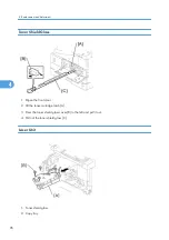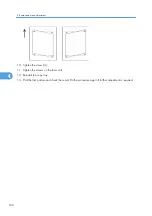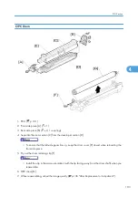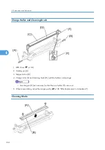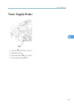
• Release the hook [B].
10. Set the coupling [C] back to the shaft.
11. Turn the coupling in the direction of the arrow [D] to remove developer from the roller.
12. Turn the bottom part [E] over and rotate the gears to remove the developer.
13. Load new developer.
14. When reassembling, execute SP 2214 to reinitialize the TD sensor.
• Make sure no toner or developer stays on the gear. Clean the gears as necessary with a blower
brush, etc.
• Be sure to replace the Mylar at the rear side in the correct position. (The Mylar protects the gears
at the rear side from falling toner).
After Replacement or Adjustment
• Do the following procedure after replace or adjust any of the PCU components. This procedure is not
necessary when you replaced the whole PCU with a new one.
1. Take 5 sample copies.
2. If black dots (dropped toner) show on any of the copies, continue as follows. (If all copies are clean,
you don't need to do the following steps.)
3. Remove the PCU from the mainframe.
4. Tap the top of the PCU with a screwdriver at eight evenly spaced locations (two or three taps at each
spot), to knock the recycled toner down into the development section.
5. Put the PCU back into the mainframe.
6. Turn the main power on. Then open and close the door and wait for the machine to rotate the
development roller for 10 seconds. Then open and close the door two more times, so that total rotation
time is 30 seconds.
7. Make some sky-shot copies (or solid black prints).
• If using A4 or 8
1
/
2
" x 11" paper, make 4 copies/prints.
• If using A3 or 11" x 17" paper, make 2 copies/prints.
• To make solid black prints, use SP 5902 pattern 8.
• Step 7 is required only after parts replacement or adjustment. You do not need to make sky-shot
(or solid black) copies after you replace the developer.
4. Replacement and Adjustment
106
4
Содержание Aficio MP 1600L2
Страница 1: ...Model K C3 5L Machine Code B244 B276 B277 B268 B269 Field Service Manual 3 December 2010 ...
Страница 2: ......
Страница 12: ...10 ...
Страница 14: ...Machine Configuration 1 Product Information 12 1 ...
Страница 20: ...1 Product Information 18 1 ...
Страница 70: ...2 Installation 68 2 ...
Страница 71: ...3 Preventive Maintenance PM Tables See Appendices for the PM Tables 69 3 ...
Страница 74: ...7 Wait until the message Completed shows 8 Quit the SP mode 3 Preventive Maintenance 72 3 ...
Страница 86: ...Platen Cover Sensor 1 Top rear cover 2 Platen cover sensor A x 1 4 Replacement and Adjustment 84 4 ...
Страница 121: ...Paper Size Switch 1 Paper cassette 2 Switch cover A x 1 3 Paper size switch B x 1 Paper Feed Section 119 4 ...
Страница 139: ...PSU Power Supply Unit 1 Left cover p 79 2 PSU A All connectors x 6 Other Replacements 137 4 ...
Страница 151: ...SP Mode Tables See Appendices for the SP Mode Tables SP Mode Tables 149 5 ...
Страница 171: ...1 1 0 0 A5 SEF 1 1 1 0 B5 SEF 1 Detected Using SP Modes 169 5 ...
Страница 207: ...Model K C3 5L Machine Code B244 B276 B277 B268 B269 Appendices 3 December 2010 ...
Страница 208: ......
Страница 210: ...2 ...
Страница 228: ...2 Appendix Preventive Maintenance 20 2 ...
Страница 262: ...MEMO 54 ...
Страница 263: ...MEMO 55 ...
Страница 264: ...MEMO 56 EN ...


