1. Start the SP mode.
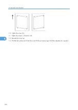
2. Select SP 5902 1 and output the ‘Trimming Area’ pattern (pattern 10).
3. Make sure that the four corners of the pattern make right angles:
• If they make right angles, you do not need to adjust the laser unit alignment.
• If they do not make right angles, go on to the next step.
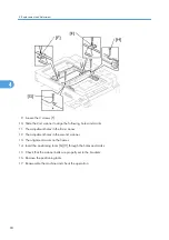
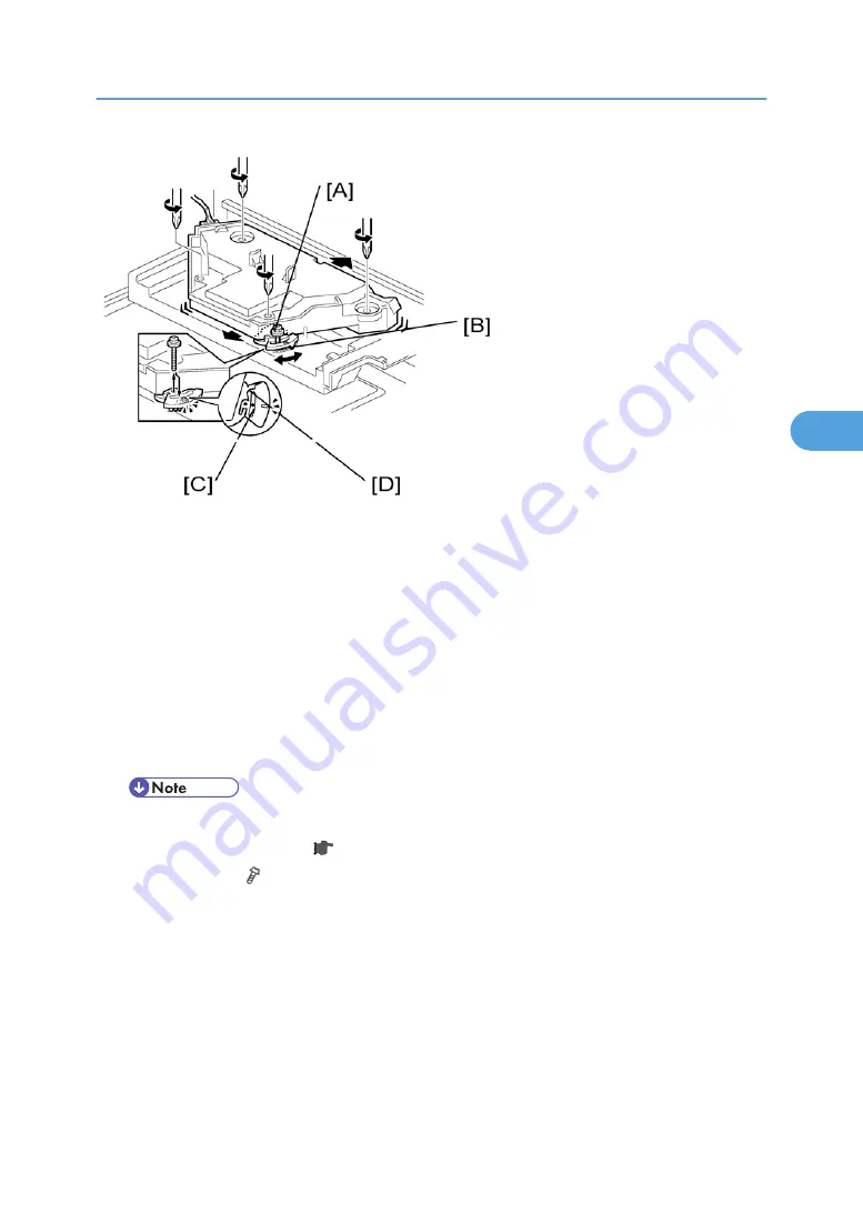
4. Check the screw position on the lever [B].
• If the screw is in the hole [C], go on to the next step.
• If the screw is in the slot [D], loosen the screw on the lever, loosen the four screws on the laser
unit, and go on to step 9.
• The initial position of the screw is in hole [C].
5. Four screws in the laser unit ( p.96)
6. Remove the lever ( x 1), confirm the position of the hole beneath the slot [D], and reinstall the lever.
7. Install the screw (through the slot [D]) loosely into the hole beneath the slot (do not tighten the screw).
8. Install the four screws for the laser unit loosely (do not tighten the screws).
9. When you rotate the lever clockwise or counterclockwise by one notch of the lever, the corners of the
pattern shift by
±
0.4 mm (from the leading and trailing edges). See the trim pattern made in step 2,
and find how much the corners should be shifted.
Laser Unit
99
4
Содержание Aficio MP 1600L2
Страница 1: ...Model K C3 5L Machine Code B244 B276 B277 B268 B269 Field Service Manual 3 December 2010 ...
Страница 2: ......
Страница 12: ...10 ...
Страница 14: ...Machine Configuration 1 Product Information 12 1 ...
Страница 20: ...1 Product Information 18 1 ...
Страница 70: ...2 Installation 68 2 ...
Страница 71: ...3 Preventive Maintenance PM Tables See Appendices for the PM Tables 69 3 ...
Страница 74: ...7 Wait until the message Completed shows 8 Quit the SP mode 3 Preventive Maintenance 72 3 ...
Страница 86: ...Platen Cover Sensor 1 Top rear cover 2 Platen cover sensor A x 1 4 Replacement and Adjustment 84 4 ...
Страница 121: ...Paper Size Switch 1 Paper cassette 2 Switch cover A x 1 3 Paper size switch B x 1 Paper Feed Section 119 4 ...
Страница 139: ...PSU Power Supply Unit 1 Left cover p 79 2 PSU A All connectors x 6 Other Replacements 137 4 ...
Страница 151: ...SP Mode Tables See Appendices for the SP Mode Tables SP Mode Tables 149 5 ...
Страница 171: ...1 1 0 0 A5 SEF 1 1 1 0 B5 SEF 1 Detected Using SP Modes 169 5 ...
Страница 207: ...Model K C3 5L Machine Code B244 B276 B277 B268 B269 Appendices 3 December 2010 ...
Страница 208: ......
Страница 210: ...2 ...
Страница 228: ...2 Appendix Preventive Maintenance 20 2 ...
Страница 262: ...MEMO 54 ...
Страница 263: ...MEMO 55 ...
Страница 264: ...MEMO 56 EN ...


