background image

Page 21

CAUTION: Unplug the vacuum cleaner before servicing.

1. Remove the nozzle cover as shown on page 10, 

II. Maintenance, B. Removing Nozzle Cover

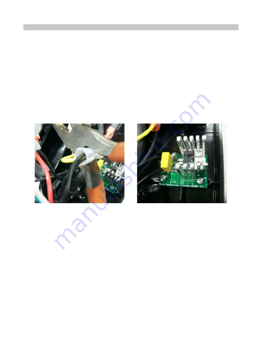
2. Remove the  (2) screws holding the PC board.  (Fig. A)

3. Disconnect the PC Board wires.(Fig. B)

4. Install the new board using the screws.  

5. Rewire the new PC board (See wiring diagram, pg. 34)

Fig. A

Fig. B

II. Maintenance

I. Replacing the PC Board (RSL4)

Содержание SUPRALITE RSL1

Страница 1: ...Ultra Lite Weight Vacuum Service Manual RSL1 RSL1A RSL1AC RSL2 RSL3 RSL3C RSL4 RSL5 RSL5C Revision 1 1 Issued 08 22 2012...

Страница 2: ...acing the Power Cord RSL2 RSL3 RSL3C RSL4 RSL5 RSL5C 16 18 G Replacing the Switch 19 H Replacing the Circuit Breaker Not present on RSL5 or RSL5C 20 I Replacing the PC Board RSL4 21 I Replacing the PC...

Страница 3: ...oor on cord or pull cord around sharp edges or corners Do not run vacuum over cord Keep cord away from heated surfaces 8 Do not unplug by pulling on cord To unplug grasp the plug not the cord 9 Do not...

Страница 4: ...Bag Nozzle Circuit Breaker RSL2 RSL3 RSL3C RSL4 Upper Cord Hook Lower Cord Hook Power Cord Handle Tube Handle Grip Handle Tube Bracket Handle Duct Furniture Guard Agitator Rear Wheels Baseplate Wheels...

Страница 5: ...per connection of the equipment grounding conductor can result in a risk of electric shock Check with a qualified electrician or service person if you are in doubt as to whether the outlet is properly...

Страница 6: ...at the top of the upper handle duct Fig A 2 Remove the handle tube bracket Fig B 3 Line up the handle tube with the posts in the upper handle duct Fig C 4 Secure the handle tube bracket over the hand...

Страница 7: ...on low speed push the handle switch to the I position To turn the vacuum on high speed push the handle switch to the II position To turn the vacuum off push the handle switch to the O position Fig B H...

Страница 8: ...the circuit breaker protector will safely shut off your vacuum cleaner to avoid any potential damage To reset the circuit breaker CAUTION Unplug the vacuum cleaner before servicing 1 Check for problem...

Страница 9: ...n Fig A 5 Close the inlet of old the bag by pulling the cardboard tab as shown Fig B 6 Install the new vacuum bag Be sure the bag collar is tucked behind the tabs as shown Fig C 7 Then press the top o...

Страница 10: ...the vacuum over so the bottom plate is showing 2 Remove the two screws holding the nozzle cover on Fig A 3 Release the two tabs located at the rear of the nozzle and remove the nozzle cover Fig B 4 F...

Страница 11: ...und the agitator and replace the agitator as shown Fig C NOTE Make sure the agitator end caps are both turned the same way The flat side should be facing the baseplate unless the brushes are well worn...

Страница 12: ...he vacuum over so the bottom plate is showing 3 Remove the baseplate by pressing the two tabs and pulling down Fig A 4 Remove the agitator 5 Discard the old belt and place the new belt around the moto...

Страница 13: ...re 5 small openings on the underside Fig B 4 Insert a small screwdriver through the openigs to push the squeegee out of the baseplate cover Fig C 5 Filp the baseplate cover back over Press the new squ...

Страница 14: ...he old wheel as shown Fig A 2 Remove wheel from axle and slide new wheel onto axle Fig B 3 Press the wheel into place until both sides of the axle lock intothe base tray It may be necessary to use a s...

Страница 15: ...power cord in place Fig A 3 Disconnect the power cord leads Fig B and C 4 Rewire power cord White wire is crimpled with white wire from motor Black wire goes to circuit breaker For assistance see wire...

Страница 16: ...A 2 Remove the 4 screws from the handle grip Fig B 3 Remove the upper cord hook and handle back and slide grip out of handle tube Fig C 4 Separate grip to expose wiring Fig D Continued on next page F...

Страница 17: ...ang out of the opening Fig A Do not put the screws in at this time 9 Line up the hole in the cord strain relief with the hole in the handle tube and the handle back Fig B 10 Insert the top of the hand...

Страница 18: ...e the black white and red leads from the PC board Fig C by squeezing the connectors with needle nosed pliers Remove the crimp nut from the green wire by squeezing it with pliers as shown in Fig B or c...

Страница 19: ...emove lead wires from switch 3 Attach wires to new switch 4 Reassemble Switch in Handle RSL2 RSL3 RSL3C RSL4 RSL5 RSL5C 1 Diassemble handle grip as shown on page 16 Section II Maintenance F Replacing...

Страница 20: ...r 2 Remove leads from circuit breaker Fig A and B 3 Squeeze the tabs on the side of the circuit breaker with needlenose pliers and push it out through the nozzle Fig C 4 Push new breaker into nozzle f...

Страница 21: ...own on page 10 II Maintenance B Removing Nozzle Cover 2 Remove the 2 screws holding the PC board Fig A 3 Disconnect the PC Board wires Fig B 4 Install the new board using the screws 5 Rewire the new P...

Страница 22: ...ll connectors from the PC board Fig B 4 Carefully clip the zip tie holding the PC board wires Fig C 5 Remove the screw holding the PC board ground wire to the idler arm Fig D 6 Remove old PC board 7 C...

Страница 23: ...ase the lower bag clip Fig B 3 Remove the cloth outer bag and set aside 4 Remove the nozzle cover as shown on page 10 II Maintenance B Removing Nozzle Cover 5 Flip the machine back over and stand it u...

Страница 24: ...ervicing 1 Access the motor as shown on page 22 Section II J Maintenance Accessing the Motor 2 Check the handle duct for clogs 3 Any clogs can be removed by running a stiff piece of wire or another ob...

Страница 25: ...the motor 2 Remove the two srews holding motor in place 3 Secure motor shaft with vice grips Fig A 4 Remove the nut from the motor fan using a 7 16 socket Fig B 5 Remove old fan from the motor shaft F...

Страница 26: ...expose the motor 2 Remove the two screws holding motor in place Fig A 3 Disconnect all wires Squeeze the wire crimp nuts with pliers to loosen them Fig B C and D 4 Secure the new motor with the two mo...

Страница 27: ...r fan and the fan duct cover seal Fig A 4 Clean both areas of all residue and replace seals Fig B Fig A Fig B Fig C CAUTION Unplug the vacuum cleaner before servicing 1 Start by following the instruct...

Страница 28: ...lly remove the hall sensor connection plug from the PC board Fig C 5 Install the new hall sensor assembly using the two screws Be sure to secure the PC board ground wire to the hall sensor base as sho...

Страница 29: ...in Fig A 2 Remove the end caps bearing cartrige and pully It may be necessary to gently pry the components apart with a screwdriver Fig B 3 Use needle nosed pliers to pull the brush strips out of the...

Страница 30: ...e is grime on the bottom plate Clean the bottom plate 3 The brushes are worn Wood agitatot Flip the agitator over or replace the agitator Steel agitator Replace brush strips 4 The wheels are not turni...

Страница 31: ...e or wired incorrectly Check the switch wiring and check the switch for continuity 2 The PC board is defective or wired incorrectly Check the wiring Replace the PC board 8 Vacuum won t stay in the upr...

Страница 32: ...age burning loose connections Replace motor if necessary See page 26 Replacing the Motor B Motor 1 Excessive vibration in motor Possible Cause Solution 1 The fan is damaged Replace the fan See page 25...

Страница 33: ...RSL1A RSLAC Power Cord M W h i t e White Yellow R e d o r Y e l l o w Black Black Bla ck Motor Lamp Power Cord Circuit Breaker Top Bottom ON OFF Switch Black Black Black Green Commercial Models Only G...

Страница 34: ...nt Handle Harness Yellow Black White ON OFF Switch Power Cord Handle Assembly Compartment o Black White M W h it e White R e d o r Y e l l o w Black Black Bla ck Motor Lamp Circuit Breaker Top Bottom...

Страница 35: ...o r Y e l l o w Black Black B la c k Black Bla ck Motor Lamp PC Board Out In Circuit Breaker Top Bottom ON OFF Switch Power Cord Handle Assembly Compartment o Black Black White Red White Green Commer...

Страница 36: ...w B l a c k Black Black Bla ck Motor Lamp PC Board ON OFF Switch Power Cord Handle Assembly Compartment o Black Black White Red White Green Commercial Models Only Green Commercial Models Only Green C...

Страница 37: ...please contact Tacony Technical Service Phone 800 643 7459 Email d humphrey tacony com Hours 6 00am 4 30pm Monday through Friday Tacony Manufacturing 3 Industrial Drive St James MO 65559 For parts or...

Отзывы: