FIRST Global Building Guide Created by REV Robotics 2019, Licensed Under CC BY-SA
35
Gears are rotating parts that have teeth and are meshed with other gears to transmit torque. Gears can be used to
change the speed, torque (turning force), or direction of a motor’s original output. For gears to be compatible with each
other, the meshing teeth must have the same shape (size and pitch).
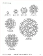
REV Robotics Gears have a 0.75 module, 20° pressure angle and are made from molded acetal (Delrin/POM). The
webbed designed with a wide face width and small tooth profile increases the gear strength without adding significant
weight. REV Robotics Gears are designed to fit a 5mm hex shaft which eliminates the need for special hubs and
setscrews. This system has seven different gear sizes with a maximum reduction of 8.3 (Table 10).
Meshing two or more gears together is known as a gear train. By selecting the gears in the gear train as larger or smaller
relative to the input gear we can either increase the output speed, or increase the output torque as shown in Figure 61, but
the total power is not affected.
When a larger gear drives a smaller one, for one rotation of the larger gear the small gear must complete more revolutions
- so the output will be faster than the input. If the situation is reversed, and a smaller gear drives a larger output gear, then
for one rotation of the input the output will complete less than one revolution
–
so the output will be slower than the input.
The ratio of the sizes of the two gears is proportional to the speed and torque changes between them.
Figure 61: Using Gears to Increase Speed or Torque
3.13.1
Correct Gear Spacing
In order for gears to work effectively, and not become damaged, it’s important that the center
-to-center distance is
correctly adjusted. The gears in
DETAIL A
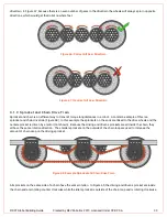
of Figure 62 may work under very light load, but they will certainly not work and
will skip under any significant loading. The gears in that example are too far apart and so the teeth of each gear barely
contact each other. The gears in
DETAIL B
of Figure 62 are correctly spaced and will provide smooth and reliable
operation.
Figure 62: Gear Spacing Example
Содержание FIRST Global
Страница 26: ...FIRST Global Building Guide Created by REV Robotics 2019 Licensed Under CC BY SA 24 Figure 40 M3 Drop in Bolt...
Страница 45: ...FIRST Global Building Guide Created by REV Robotics 2019 Licensed Under CC BY SA 43 GEARS 1 1 Scale...
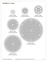
Страница 46: ...FIRST Global Building Guide Created by REV Robotics 2019 Licensed Under CC BY SA 44 SPROCKETS 1 1 Scale...
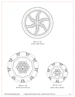
Страница 47: ...FIRST Global Building Guide Created by REV Robotics 2019 Licensed Under CC BY SA 45 WHEELS 1 1 Scale...
Страница 49: ...FIRST Global Building Guide Created by REV Robotics 2019 Licensed Under CC BY SA 47 BRACKETS 1 1 Scale...
Страница 50: ...FIRST Global Building Guide Created by REV Robotics 2019 Licensed Under CC BY SA 48...

