


REOVIB MFS 268 UL/CSA
Operating Instructions
3
ELEKTRONIK
1.0 General
The REOVIB MFS 268 range comprises special, adaptable controllers for use with vibratory feeders. The
units generate an output frequency, to drive feeders, that is independent of mains frequency and so exact
tuning with springs is not necessary. The feeders also run quieter because of the sinusoidal output signal.
The adjusted output frequency corresponds to the mechanical vibrating frequency of the feed system.
The optimum frequency setting for a feeder can determined manually or automatically in regulation mode.
Depending on the version, the controller can be used in regulation mode, working in conjunction with an
accelerometer fitted to the feeder, to operate at resonant frequency. In this way a constant component
feed rate that is unaffected by load changes can be achieved. In regulation mode the vibrating frequency
is also dynamically adjusted to compensate for resonant frequency changes caused by load changes. In
normal operating mode (without accelerometer) the feeder remains constant at the set frequency. In both
operating modes the feeder throughput is determined by the output voltage level.
Totally enclosed or panel mounting units can be supplied.
Notable Features:
•
Adjustable output frequency, independent of mains fre-
quency
•
Adjustable minimum and maximum limits for the frequen-
cy range
•
Adjustable current limit for the maximum coil current
•
Constant feeder throughput irrespective of mains fluctua-
tions
•
Regulation control, with independent frequency search
(resonance)
•
On/Off status relay
•
Track control
•
24 VDC output for operating a solenoid e.g air valve
•
Four user setting memory locations
•
Optional RS232 or Profibus-DP interface for remote pa-
rameter setting.
2.0 Function
The unit is set up by using the touch panel on the front plate (buttons and LED display). All settings can
be made by using the touch panel and a series of menus. The various parameters can be selected by
entering operator codes. A fuller description of the parameters can be found In the section on settings.
Alternatively, the feeder throughput can adjusted by using an external potentiometer, an external voltage
signal 0...10 V, DC or a current signal 0(4)...20 mA (the chosen option must be selected in menu 003). A
relay with potential free contacts is provided for feeder status indication and this operates in conjunction
with the feeder enable signal. Terminals for these contacts can be found inside the controller.
During normal operation the set point is displayed as a percentage in the LED window. In the program-
ming mode the selected dimension, as described in the setting up instructions, is shown. Changed set-
tings can be stored by leaving the programming mode or automatically saved by not pressing a key for a
period of 100 seconds.
The control units can provide a frequency range from 5…300 Hz, which can be limited by adjustable,
upper and lower frequency limits. The usable adjustment range cannot exceed a ratio of 1:4, i.e. the up-
per frequency limit cannot be more than four times the lower frequency limit. It is possible to have a nar-
rower setting of the limits and this provides a margin of safety against too wide a difference in the vibrat-
ing frequency.
The maximum output current drawn by the coil can be determined by integrated current limiting.
Critical parameters such as the current limit and vibrating frequency range are held under a special ser-
vice menu. This menu cannot be accessed through the normal menu structure and an additional code
number has to be used to gain access. This prevents unauthorised adjustment of these sensitive parame-
ters.
An interface option can be used to provide an RS232 or Fieldbus (Profibus-DP) connection.
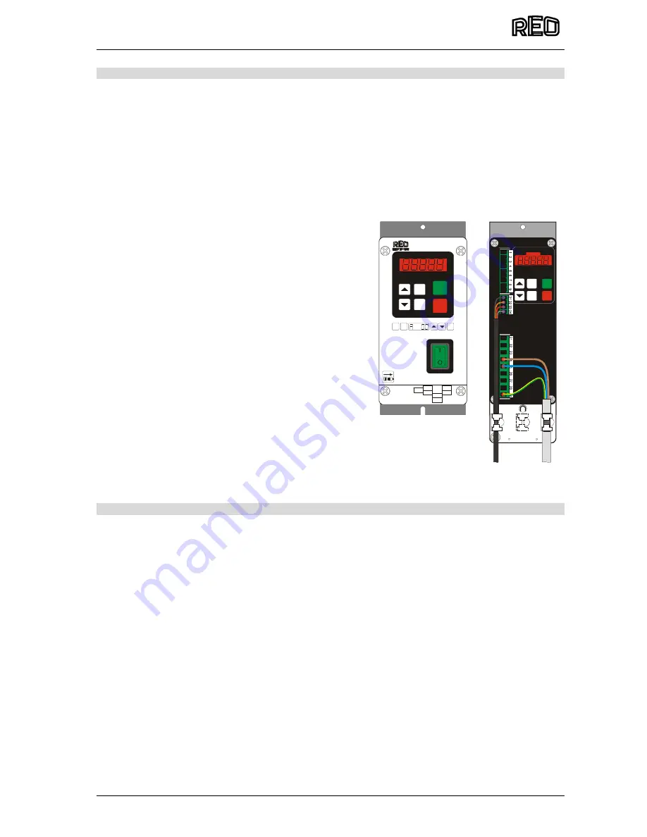
Enclosed
Construction
Panel mounting
construction
Ø 5,0
2
1
2
2
2
3
2
4
2
5
2
6
2
7
2
8
2
9
1
2
3
4
5
6
7
8
9
3
1
3
2
3
3
3
4
REOVIB MFS268
F
I
0
P
SPEED
P
P
P
REOVIB MFS 268
X1
X4
X7
X6
X0
X40
X5
P
F
I
0
www.reo.de


