Renkforce RF500 Maker Construction Kit Скачать руководство пользователя страница 60

60

c) Mounting of the door

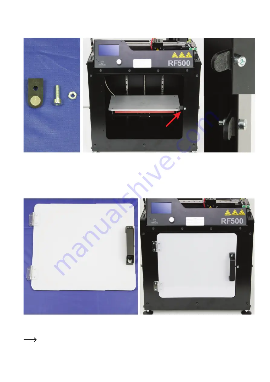
Attaching the magnet holder

1x magnet holder

1x cylinder head screw M5x16

1x screw nut M5

Attach the magnet holder to the front side of your printer using the M5 cylinder head screws as shown in 

the picture. In doing so, align the holder straight. Furthermore, the magnet must point towards the inside 

of the printer.

The order is: 

Cylinder head screw - metal housing - magnet holder - screw nut

Mounting of the door

1x door with attached hinges and handle

4x cylinder head screws M3x12

4x screw nuts M3

 Please note! The screws and nuts are depicted slightly 

bigger.

Fasten the hinges of the door to the front of your printer using the M3 

cylinder head screws and screws as shown in the picture.

The order is: 

Cylinder head screw - hinge - metal housing - screw 

nut

Содержание RF500 Maker Construction Kit

Страница 1: ...Heatable Printing Bed Item no 1550421 Item no 1600018 for Z expansion Aluminium Die Cast Plate Item no 1544299 Heating Mat Item no 1544298 Item no 1599746 for Z expansion LED Light Strips Item no 1553...

Страница 2: ...embly of the new printing plate 14 d Connection of the electrical lines 15 e Conversion of the mains unit 16 f Important additional information 17 9 Assembly of LED light strips 18 10 Assembly of Z ex...

Страница 3: ...e symbol with a lightning bolt in a triangle is used where there is a health hazard e g from electric shock The device contains no parts that require servicing by the user Therefore never open the dev...

Страница 4: ...u Using the product for any other purposes than those described above may damage the product Improper use also may cause dangers such as short circuit fire electric shock etc Read the operating instru...

Страница 5: ...s a digital download Acrylic housing Item no 1761572 1 x dome front plate 1 x dome top plate 1 x dome rear plate 2 x dome side plate 1 x door 1x handle 2x hinges 1 x magnet holder 21 x cylinder head s...

Страница 6: ...ts Do not leave any packaging material unattended It may become a dangerous toy for children If you are not sure of the correct connection or if there are any questions that are not covered by the ope...

Страница 7: ...workshop Never place any sources of open fire such as lit candles on or right next to the device When setting up the mains unit make sure that the mains cable is not pinched or damaged by sharp edges...

Страница 8: ...1 Metal housing side panel right 2 Metal housing rear panel 3 Metal housing side panel left 4 Aluminium die cast plate 5 Heating mat 6 Metal housing bottom panel 7 Metal housing front panel Not illust...

Страница 9: ...9 b Z expansion 1 Longer spindle 571 mm 2 2 x aluminium profile 600 mm with 2 x guide rail with guide carriage 640 mm 3 4 x aluminium profile 676 mm Not illustrate 1 x aluminium profile 137 mm 1 3 2...

Страница 10: ...ightly Many screws are turned into aluminium threads and therefore must not be tightened as far as it would be possible e g in steel threads If you install accessories directly when installing the con...

Страница 11: ...n the respective screw in the slot nut always make sure that the slot nut is placed cleanly in the nut If you have to take out the slot nut push it to the side so that it slips from the guide Then tur...

Страница 12: ...mains unit from the main PCB a Disassembly of the original printing bed First remove the two holding brackets of the printing plate Then carefully remove the glass support from the printing plate You...

Страница 13: ...of dust and grease with a rag and solvent Remove the protective film from the adhesive side of the heating and glue it to the new printing plate without any folds and blisters Press on the heating wel...

Страница 14: ...tic Place a pressure spring on each screw of the printing plate and guide them through the bores in the undertable Push the plate from above push one spacer each onto the respective screw from below a...

Страница 15: ...ant for this Connect the plug for the temperature sensor to connection T1 The polarity does not matter for this either Fasten the cable with a cable tie For this also observe the next figure the adjus...

Страница 16: ...inus Now connect the white double line of the mains unit to the left terminal of the plug The 2nd terminal from the left holds the black double line of the mains unit The 3rd terminal must have the re...

Страница 17: ...ion of the main instructions of the RF500 First set the Z end stop Then set the printing plate Always make these settings in the hot condition from now on Heat up the printing bed to approx 60 C for t...

Страница 18: ...ED strip to the printer The first option is at the upper alu minium profile on the left where the cable for the display is running as well The other method would be in the area of the main PCB If you...

Страница 19: ...nds on whether the LED strip completely fits the profile and whether its cable can still be attached to the adhesive base Glue the LED light strip to the front aluminium profile Do not glue the strip...

Страница 20: ...erve the circuit diagram see figure below and the enlarged figure at the upper right Always observe the proper polarity Otherwise the LED strip the main PCB and the mains unit can be destroyed Attach...

Страница 21: ...installed the heating mat remove the connection cable of the heating mat from the connection terminals of the main PCB Also remove any cable ties with which the cable is attached Move the table up unt...

Страница 22: ...he Y motor cable and the cable for X are attached to the upper aluminium profile Remove all adhesive bases here as well Removing the cable from the Z motor Disconnect the cable from the Z motor Remove...

Страница 23: ...he two M5 cylinder head screws and remove the infeed unit Remove the adhesive base and the two slot nuts from the aluminium profile Disassembly of the spindle Remove the two cylinder head screws that...

Страница 24: ...ve all 8 M3 cylinder head screws that attach the table to the guide carriages Always remove a left and a right one alternatingly Take out the table and put it aside Remove the two M3 cylinder head scr...

Страница 25: ...ched Removing the end caps Finally remove the 4 end caps that are plugged to all 4 vertical alu minium profiles It will be easiest to lever them out carefully with a flat head screw driver or similar...

Страница 26: ...guide rail with guide carriage 640 mm 2 x cylinder head screw M5x20 14 x cylinder head screw M3x8 10 new and 4 present 14 x slot nut M3 10 new and 4 present Assemble the 3 aluminium profiles as illust...

Страница 27: ...ightly Remove the 4 green circlips only after installation in the printer If you have purchased the matching heating mat with the longer cable for the Z expansion as well you can prepare the printing...

Страница 28: ...pective bore always must point to the out side The screw is always pushed in from this side as well Aluminium profile 1 front left Aluminium profile 2 front right Aluminium profile 3 rear left with cu...

Страница 29: ...e the 4 M5 cylinder head screws that attach the profile Remove das aluminium profile from the printer Remove the foot from the disassembled aluminium profile and put it aside The short aluminium profi...

Страница 30: ...the foot from the disassembled aluminium profile and put it aside The short vertical aluminium profile is no longer needed Insert the long aluminium profile into the printer and attach it at the top...

Страница 31: ...ng Observe the washer Pull the shaft from the ball bearing on the right side and put it aside Remove the foot from the disassembled aluminium profile and put it aside as well Carefully lever the ball...

Страница 32: ...of the short profile and insert it into the long aluminium profile The short profile with the cut out is no longer needed The upper bores and cut outs of the long and short alu minium profiles are ide...

Страница 33: ...se profile from above The side where the green circlip was removed must be threaded through the Z limit switch holder Attach the guide rail holder with 2 M5 cylinder head screws Tighten both screws ha...

Страница 34: ...When you have attached all screws loosely tighten them in the order in which you have screwed them in Optionally the screws can be secured with threadlocker varnish Push the undertable all the way up...

Страница 35: ...the two guide rails evenly in height Move the undertable up and down manually several times Move the undertable all the way down Then tighten the bottom most screw of the 1st guide rail Move the under...

Страница 36: ...the vertical aluminium profile back into the starting position and push the deflection shaft into the left ball bearing Insert the two M5 cylinder head screws previously removed again and tighten the...

Страница 37: ...onents to the printer again relieve it completely first Release all M5 cylinder head screws that attach the 4 vertical aluminium profiles to the transverse profiles for this You only need to release t...

Страница 38: ...Tension the belt and align the holder straight Then tighten the screws Take the disconnected cable for the Y motor and connect it to the motor plug from the inside Remove the 3 other green circlips fr...

Страница 39: ...le tie Thread the cable from the inside through the cable feedthrough above the main PCB and connect it to the connection for the Z motor Ensure correct polarity The brown pin of the cable must be on...

Страница 40: ...er Attach the infeed unit to the slot nuts loosely with the two M5 cylinder head screws Push the filament tube back into the quick closure and align the infeed unit in height Tighten the two attachmen...

Страница 41: ...re spring for printing table length 24 mm 4 x spacer 7 mm diameter inside 4 2 mm 4 x knurled nut black plastic Place a pressure spring on each screw of the printing plate and guide them through the bo...

Страница 42: ...sensor to connection T1 The polarity does not matter for this either For this also observe the adjusted terminal plan of the main PCB see next figure Limit switch Z 02 Limit switch X 01 Limit switch...

Страница 43: ...tach only the lines for the Z motor to the two lower ones Also attach the line for the Z motor and for the heating mat to the upper base with a cable tie Attack all lines cleanly with cable ties to th...

Страница 44: ...d if present Tighten all M5 cylinder head screws to a torque of 3 Nm a Preparation of the printer Newly place the connection line for the Z motor First the connection line for the Z motor is newly ins...

Страница 45: ...so remove the cable tie and adhesive base incl glue residue that attach the extruder cable on the side Route the line for the Z motor through the feedthrough at the PCB holder on top and place the cab...

Страница 46: ...asten the plug on PCB by pushing the X guide rail towards the PCB holder Remove both M5 cylinder head screws of the PCB holder and take it off Leave the two slot nuts in place You will need them later...

Страница 47: ...47 Removing the filament holder Remove the filament holder by turning out the M5 cylinder head screw on the inside Put the filament holder aside You will only need it again in the end...

Страница 48: ...M2 5x16 plastic 3 x nut M2 5 plastic Attach the main PCB to the rear panel The rear panel and the main PCB must be aligned as illustrated Begin with the left screw at the middle of the PCB Install the...

Страница 49: ...ylinder head screws Attaching the main PCB Attaching the lines for the Z motor and the heating plate Fold down the additional PCB again and plug it onto the main PCB Ensure that all pins are placed in...

Страница 50: ...nium profile Generally align all 8 slot nuts The threads should be aligned as illustrated Hold the side panel against the printer and align all slot nuts precisely with the bores in the side panel Att...

Страница 51: ...ent holder Attach the lines for the extruder to the rear panel or the left side panel with adhesive bases and cable ties see arrows in the figure Push the filament holder through the left side part in...

Страница 52: ...inium profile Generally align all 8 slot nuts The threads should be aligned as illustrated Hold the side panel against the printer and align all slot nuts precisely with the bores in the side panel At...

Страница 53: ...rofile Generally align all 5 slot nuts The threads should be aligned as illustrated Hold the front panel against the printer and align all slot nuts precisely with the bores in the front panel Attach...

Страница 54: ...n all 7 slot nuts The threads should be aligned as illustrated Hold the bottom panel against the printer and align all slot nuts pre cisely with the bores in the bottom panel Attach the bottom panel t...

Страница 55: ...he instructions this protective film has been removed on one side only In general we recommend removing the protective film only once mounting is complete For the assembly it is sufficient to remove t...

Страница 56: ...cylinder head screws slightly at first so that nothing can move Tighten all screws well only at the end when the entire dome is assembled However do not tighten the screws too much since the plastic...

Страница 57: ...screws to the rear plate as shown in the picture 1x rear plate A3 with both side plates attached A4 not shown in the picture 1x top plate A2 5x cylinder head screws M3x12 5x screw nuts M3 Please note...

Страница 58: ...each of the remaining sloped front side of the two side plates Remove the protective film on both sides in the respective areas Fa sten the front plate with 4 M3 cylinder head screws as shown in the...

Страница 59: ...y the magnet It is inserted into the door from the outside i e the side where you can touch the magnet directly is on the outside The order is Cylinder head screw hinge door screw nut Attaching the ha...

Страница 60: ...e magnet must point towards the inside of the printer The order is Cylinder head screw metal housing magnet holder screw nut Mounting of the door 1x door with attached hinges and handle 4x cylinder he...

Страница 61: ...erted previously Align both hol ding blocks in such a way that they make contact with the front profile and the sloped side is pointed towards the front side Attaching the dome Place the assembled dom...

Страница 62: ...55 x 6 mm Weight 715 g b Heating mat Operating voltage 12 V DC Power input max 16 A Max power intake 120 W Temperature max 135 C Dimensions W x H x D 290 x 155 x 9 mm Weight 210 g c Mains unit Operati...

Страница 63: ...m Rear panel 399 x 356 mm Side panel left 325 x 356 mm Side panel right 325 x 356 mm Thickness of the housing parts 2 5 mm g Acrylic housing Printer dimensions W x D x H approx 500 x 400 x 580 mm Dime...

Страница 64: ...any kind e g photocopy micro filming or recording in electronic data processing systems require the written approval of the publisher No part of this publication may be reproduced This publication cor...

Отзывы: