


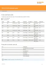


Head connector cables
PHC = probe head cable
MC = machine cable
MC
MC
MC / PHC
PHC
PHC
Signal name
15-way male 'D'
type
Cable PLM 6 - 9
14-way LEMO
12 core cable
14-way Tuchel
socket
Max line current
B-axis feedback
14
Black
(F) 1 (M)
Yellow
E
n/a
Ground sense
1
Brown
(F) 2 (M)
Red
D
n/a
DC reference 12 V 6
Violet
(F) 3 (M)
Brown
C
12 mA
0 V
4
Green / red
(F) 4 (M)
Grey
M
1000 mA
Locking motor 8
V dc nominal
10
Green
(F) 5 (M)
White
H
350 mA
A-axis motor 12 V
dc nominal
12
Red
(F) 6 (M)
Green
L
350 mA
Head present
2
Turquoise
(F) 7 (M)
Not connected
-------
-------
A-axis motor 12 V
dc nominal
11
White
(F) 8 (M)
Dark blue
F
350 mA
B-axis motor /
probe contact
7
Pink
(F) 9 (M)
Violet
A
350 mA
B-axis motor /
probe contact
15
Orange
(F) 10 (M)
Black
B
350 mA
Screen
Body
Screen
(F) 11 (M)
Screen
N, O
-------
A-axis feedback
3
Yellow
(F) 12 (M)
Orange
G
n/a
LED and datum
8
Blue
(F) 13 (M)
Turquoise
J
15 mA
Motor probe
switch
5
Grey
(F) 14 (M)
Pink
K
40 mA
NOTE:
The male pins numbered 4 and 7 of the 14-way LEMO connector are linked together.
PHC10-3 PLUS installation guide
www.renishaw.com
Issued 12 2021
34


